Flow allocation
Arguably the most important concept to grasp in Ouroboros is flow allocation.1 It is the process by which a pair of programs agree to start sending and receiving data, and the interface to the network. A flow is always unicast, thus between a source program and a destination program, and is always established from the source. Flows are provided by unicast layers, and the endpoints of the flows are accessible for reading and writing by the requesting processes using an identifier called a flow descriptor. Think of a file descriptor but just for Ouroboros flows. Maybe one important thing to keep in mind: in Ouroboros terminology, a flow does not imply ordering or reliable transfer. It just denotes the network resources inside a layer that are needed for forwarding packets from a source to a destination in a best effort way.
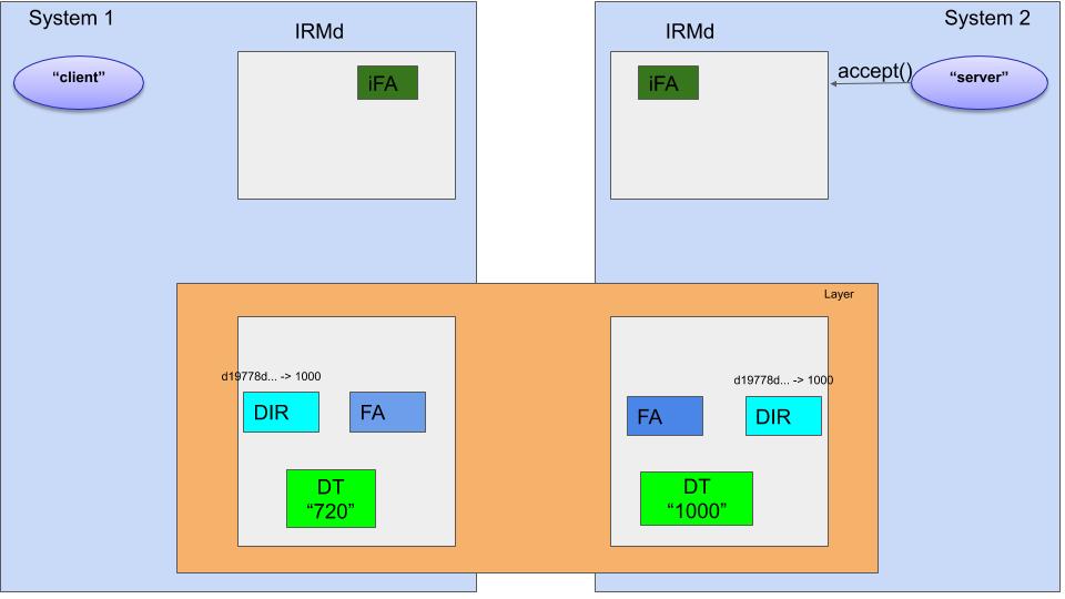
The figure above gives an example. There are 2 systems, and each system has an Ouroboros IRMd and a unicast IPCP. These IPCPs work together to create a logical “layer”. System 1 runs a “client” program, System 2 runs a “server” program.
We are going to explain in some detail the steps that Ouroboros takes to establish a flow between the “client” and “server” program so they can communicate.
The three subcomponents inside the IPCP that are of interest to us are the Directory (DIR), the Flow Allocator (FA) and the Data Transfer component (DT).
The DT component is at the heart of the network functionality in the layer. It is a protocol machine responsible for forwarding packets and maintains a forwarding table that maps destination addresses to lower layer flows. 2 The name of the DT is what is generally considered the “address” of the IPCP. 3 In the example, IPCP 1 has address 720, and IPCP 2 address 1000. If DT 720 receives a packet for DT 1000, it will know how to forward it to 1000 and vice versa. I will not go into the details of how routing information is distributed, suffice to say it’s similar in operation to the IS-IS protocol. The only other thing that is of current interest is the protocol format of the DT component. The DT protocol has 5 fields 4:
DST | TTL | QoS | ECN | EID |
To understand the flow allocation procedure, we need to consider only 2 of these fields, the destination address (DST), and the endpoint ID (EID). I will denote the relevant packet header information for DT in the format DST:EID So, 1000:78 would indicate a packet destined for IPCP 2 with EID 78. EID’s are a bit like a tcp port, but they are not well-known (i.e. there is no IANA in Ouroboros). The flow allocation process will assign the EIDs.
The directory (DIR) component keeps a mapping of registered hashes to DT names (addresses). For the server application to be reachable over a layer, the DIR component in its IPCPs will have to know this mapping. In our example, the server, which is named server is known by the layer to be at location 1000. The interface to register a name is actually using hashes, so “server” is hashed (by default an SHA3-256 hash) to d19778d25 and a mapping (d19778d2, 1000) is kept in the directory. The default implementation for the DIR component in the Ouroboros IPCP is a Distributed Hash Table (DHT) based on the Kademlia protocol.
The third subcomponent in the IPCP that is relevant here – the most important one – is the Flow Allocator (FA). This component is responsible for implementing and managing requested flows. It is also responsible for congestion control.
For establishing a flow, it needs to establish some shared state between the two endpoints. A (bidirectional) flow is fully identified in a layer by a 4-tuple (A1,X,A2,Y) containing two addresses and two EIDs, in our example A1=720 and A2=1000). This 4-tuple needs to be known at both endpoints to identify where to send the packets it receives from the higher-layer application (the client), and to deliver packets that it reads from a lower layer flow. The flow allocation protocol is responsible to send this information. It is a request-response protocol. The flow allocator is identified by the DT component as EID 0. So, all packets in the layer with DT header DST:0 are delivered to the flow allocator inside the destintation IPCP.
When the source FA in IPCP 1 receives a request for a flow to “server”, it will query its DIR for d197782 and receive 1000 as the response and it will generate an EID (X) for the flow. Let’s assume X=75. The flow allocation request protocol message from FA 1 to FA 2 looks like 1000:0:REQ:720:75:d19778d2, and when FA 2 received this message, it will generate its EID, let’s say 81 and send the following response to FA 1: 720:0:RESP:75:81. REQ and RESP are internal codes to identify a request and reponse (0 and 1 respectively). From this small exchange both flow allocators can now identify the flow.
Finally, there is the IRMd in each system. The IRMd should be seen as part of the operating system. One of its tasks is to map process IDs (PIDs) of a process to names. In our example above, the IRMd in System two will have a mapping that maps d19778d2 to the PID of “server”. When the “server” program calls the Ouroboros flow_accept() routine, the IRMd knows that when there is an incoming flow allocation request, the “server” process can handle it. Populating this mapping in the IRMd is a process we call binding a name to a process.
Let’s now go step-by-step through the full flow allocation process in the example above.
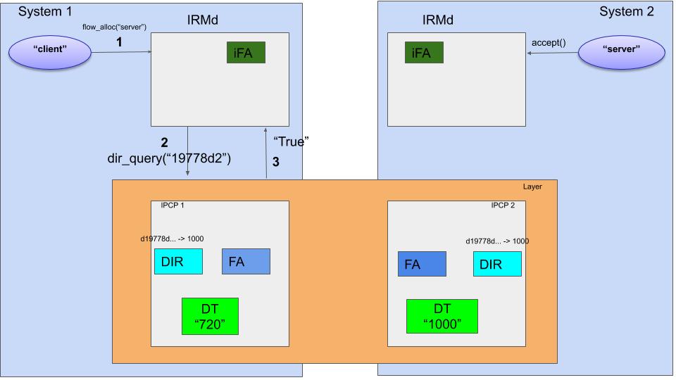
The first few steps are shown in the figure above. The client application requests a flow to “server” to the Ouroboros IRMd using the flow_alloc() call (1). Now the IRMd will ask the layers in the system if they know that name “server”, indirectly by using the SHA3-256 hash, d1977d2 (2). The hash algorithm that a layer uses is configurable, and the IRMd is informed of the hash algorithm to use when an IPCP joins a layer (at bootstrap or enrollment). In our case, the layer shown will respond to the query with “True” (3), (multiple layers can respond true, and then the IRMd will choose one, usually the “lowest” in rank). Note that the results of these queries can be cached locally in the IRMd to speed up the process.
So, now that the IRMd knows that the layer in the figure knows the destination program, it can send a flow allocation request to the layer. But first, it will start creating some local resources: the flow endpoint, indicated by a flow_id (FID) (4). It contains a set of ring-buffers in shared memory that contain pointer information on where to read/write the next packet. The FID will be in PENDING state 6.
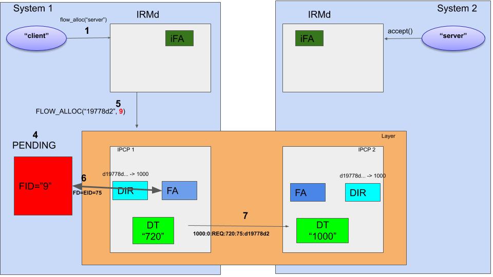
When the FID resources are ready, the IRMd sends a FLOW_ALLOC to the IPCP with the pending FID as endpoint (5). The FA in IPCP 1 will create a flow descriptor for this flow 7, let’s say 75 (6). All packets that are written by the IPCP to fd 75 can be read from FID 9. Now, a couple of paragraphs ago I mentioned that the FA will generate an EID for the flow. In the implementation, the EID for the flow equals the fd. So packets coming from within the layer with EID 75 will be written to this flow.
This is the point where the FA will do the flow allocation protocol exchange already described above. The destination hash is resolved from the directory to the destination IPCP address, 1000, and the following flow allocation request message is sent over the DT component to the destination IPCP: 1000:0:REQ:720:75:d19778d2 (7).
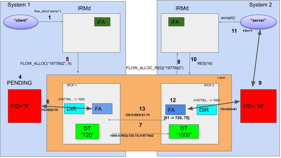
We can now turn our attention to System 2, which receives this request message on IPCP 2. The DT header contains 1000:0 which has the correct address (1000) and EID 0, which indicates the packet should be delivered to the flow allocator. So the FA interprets the following information from the received packet: There is a flow allocation request for the hash d19778d2 coming from source 720 on remote EID 75.
Now it send a FLOW_ALLOC_REQ() message to the IRMd (8). The IRMd has in its process table an entry that says that there is a process that listens to this hash. It will create a flow endpoint, for instance with FID=16 (9) and respond to the IPCPd that the flow is accepted with FID=16 (10). The flow_accept() call on the server side will return with an fd=71 that points to the FID 9. From this point on, the server can use the flow (11).
The flow allocator in IPCP 2 can now complete its enpoint configuration. It will create a mapping [S_EID -> R_ADDR, R_EID], in this case [81 -> 720, 75]. So all packets that it reads from EID 81 will get a header 720:75 from the DT component (12). It will now complete the flow allocation protocol and send a response message that flow allocation succeeded. The contents of this message is 720:0:RES:75:81 (13). This concludes all operations on the server side.
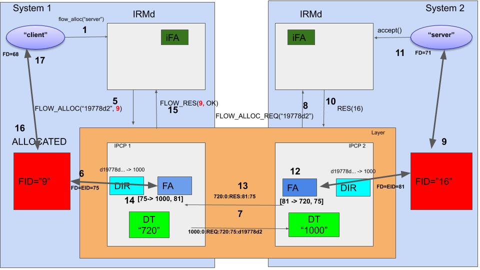
Back to the client. The FA in System 1 receives the packet, and from EID 0 knows it is for the flow allocator, which gets its last piece of information: the remote EID for the flow, 81. It can now create its own mapping, [75->1000, 81] (14) and respond to its IRMd that the flow is created (15). The IRMd will change the state of the flow from PENDING to ALLOCATED (16) and the flow_accept() call on the client program will return with an FD for the flow. The flow is now allocated.
So, from now on, communication between the server and the client is pretty straightforward. Data is written to some shared memory in an buffer that allows for some space to prepend headers and append CRCs. To avoid memory copies, pointers to these locations are passed over the ringbuffers in the flow endpoints to the IPCP, which reads the pointers, adds headers in the right location, and then uses the same procedure to pass it onto the next layer towards the destination. The translation of the header is an O(1) lookup on the send side, and a nop on the receiver side (since FD == EID and it’s passed in the packet).
- This concept is also present in RINA, but there are differences. This text only applies to Ouroboros. [return]
- This is a recursive network, adjancencies in layer N are implemented as flows in layer N - 1. [return]
- If there is one DT, it is what is usually considered a “flat” address. More complex addressing schemes are accomplished by having more of these DT components inside one IPCP. But this would lead us too far. It is described in more detail in the paper. [return]
- I will explain QoS in a different post. [return]
- In full: d19778d2e34a1e3ddfc04b48c94152cced725d741756b131543616d20f250f31. [return]
- Note that the flow_alloc() call 1 is currently blocking. Asynchronous allocation implementation is on the TODO list. [return]
- All this mapping of fd’s is done by the library that is used by all Ouroboros programs. [return]