Ouroboros Functional Layering
The Ouroboros model is the result of countless architectural refinements made during the (still ongoing) implementation of the Ouroboros prototype. The layered model treats broadcast/multicast as distinct from unicast. All layers in the model have a well-defined service API, which allows them to appear as black boxes to one another.
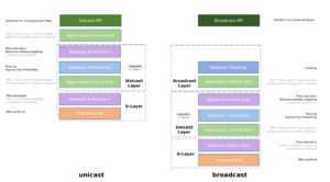
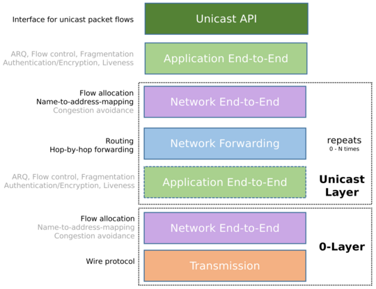
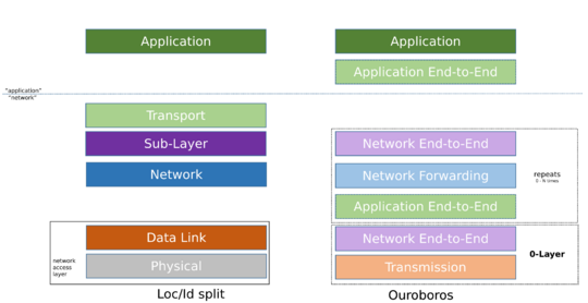
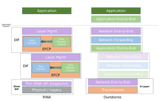
The unicast model has 5 layers: the application layer, the application end-to-end layer, the network end-to-end layer, the network forwarding layer and the transmission layer.
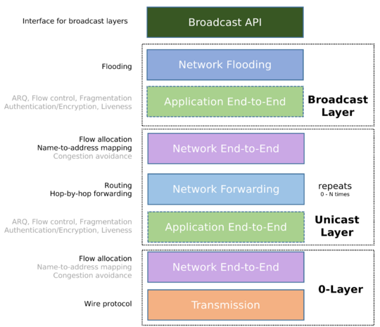
Broadcast is implemented by a network flooding layer.
Applications request network services using the Unicast API and/or Broadcast API.
For unicast, the application end-to-end layer interfaces with the network-end-to end layer via the Network IPC API, which is invisible to the application itself. The network IPC API forms the demarcation line between 'the application' and 'the network'.
The Broadcast API interfaces directly with the network flooding layer. Furthermore, a network (both of the unicast and broadcast variant) is seen as a distributed application, so it also inherits the application end-to-end layer, giving rise to a repeating network structure.
This page provides an overview of this model as it currently stands, and some insights in how it compares to other models such as the TCP/IP Internet, Location/Identifier split and the Recursive InterNetwork Architecture (RINA).
Unicast model
Unicast API
The Unicast API provides the interface for an application to create, manage and destroy unicast flows and read and write from and to these flows. The API is network-agnostic and provides application primitives for synchronous and asynchronous Inter-Process Communication. It supports message-based and (byte)stream-based communication.
Application end-to-end layer
The application end-to-end layer provides the functionality to establish flows and make packet transmission on that flow reliable and secure. Unicast flows are initiated by a client process towards a server process, identified by a service name.
The application end-to-end layer can provide the following operations:
- Encryption (Symmetric key)
- Reliability, implemented by the FRCP protocol
- Fragmentation
- In order delivery
- Discarding duplicate packets
- Automated-Repeat Request (ARQ)
- Flow control
- Integrity (hash-based checks such as CRC32)
- Liveness monitoring
All the above functionality is optional, and if reliability (FRCP) is disabled, we call the service a raw flow.
Establishment of the flow, authentication and symmetric key distribution are implemented using a 2-way handshake each. If the MTU allows, the authentication and symmetric key exchanges can be piggybacked onto the flow establishment request/reply in a single combined 2-way exchange, so within a 1 Round-Trip Time. See Flow Allocation for more details.
The application end-to-end layer uses the network IPC API to interface into the network end-to-end layer below.
Network end-to-end layer / Flow Allocator
The network end-to-end layer is responsible for creating a network flow in a suitable Unicast Layer between two Unicast IPCPs (designated the source and destination IPCP) that implements a client flow (between two end-user processes, designated the client process and server process). The source and destination IPCP reside in the same systems as the respective client and server end-user processes.
We often refer to the Network End-to-End layer as the flow allocator after the core component in the IPCP that implements it.
It provides four core functions:
- Name-to-address resolution: given a service name, find an address for a suitable IPCP that can serve as a destination for the network flow. The directory service holds this mapping for the layer.
- Flow allocation: create shared state between the source and destination IPCP associated with a flow
- Multiplexing: generate a local Endpoint Identifier for a flow
- Map this local Endpoint Identifier to the peer address
- Congestion avoidance: Monitor the network flow for congestion and police throughput as needed.
The network-layer flow allocation exchange maps the application-requested QoS to a network traffic class. The application-level request/response is carried over by the network-level request/response handshake to fit the complete flow allocation process (application-level and network-level) within a single round-trip.
The network end-to-end layer provides the interface for the application end-to-end layer on top, so these two layers always go hand-in-hand.
Network Forwarding layer
The network forwarding layer is responsible for forwarding Ouroboros Data Transfer Protocol packets from the source IPCP to the destination IPCP, based on their addresses and QoS class.
The forwarding function takes the destination address and decides on which flow(s) to forward the packet, usually implemented as a table (forwarding table). In order to do this, distance information needs to be available at each IPCP, which we call the routing dissemination function.
Transmission layer
At the bottom we find the 'Transmission layer', which is the abstraction for a point-to-point communications channel whose operation is completely independent to all other components of O7s. This can be the wire protocol over a physical medium (copper wire, wireless broadcast, machine RAM, ...) or a network technology such as Ethernet, IP, UDP, Bluetooth, ... to allow constructions as O7s-over-UDP, O7s-over-Ethernet.
This Transmission layer is best seen as a special case of the network forwarding/flooding layer to build a 0-Layer to stop the recursion. It is coupled to its own specifically tailored network end-to-end layer to interface with the application end-to-end layer above (as these 2 end-to-end layers always go hand-in-hand). This network end-to-end layer at least needs to implement a minimal flow allocator if the tranmssion layer is a dumb link, but when the transmission layer wraps a legacy network technology, it may be beneficial to have all features of a network-end-to-end layer.
Broadcast model
The broadcast model has two main additions to the unicast model, the Broadcast API and the network flooding layer.
Broadcast API
The Broadcast API provides the interface for an application to join and leave broadcast flows, and read and write from and to such flows. The API is network-agnostic and provides application primitives for synchronous and asynchronous IPC. It supports message-based and (byte)stream-based communication. QoS for Broadcast flows is (inherently) limited when compared to the options available for Unicast Flows. A Broadcast flow maps directly to the concept of a Broadcast Layer (see below).
Network Flooding layer
The network flooding layer is responsible for flooding packets from the input data transfer flow to all other data transfer flows. This operation is in essence stateless.
The network flooding layer interfaces with an application end-to-end layer to provide the data-transfer flows that make up the links of the Broadcast Layer, which typically form a tree (but a Directed Acyclic Graph is a sufficient condition).
Layers and recursive networking
As an application end-to-end layer pairs with a corresponding network application end-to-layer, and the network flooding and network forwarding layers are part of a network application, it is clear that the Ouroboros Unicast Model gives rise to a 'ham-and-cheese sandwich' structure that can be stacked repeatedly. If the network IPC API between the application and network end-to-end layers is a single universal standard, then all the Layers (capital L) in this sandwich can be moved around at will. This is what is called a recursive network. The Ouroboros model hints very strongly at recursion, but does not require it.
Unicast Layer
The Unicast Layer consists of a three-layer application that contains implementations of a network end-to-end layer and a network forwarding layer (and inherits the application end-to-end layer). This (abstract) application is called a Unicast IPCP. The Unicast IPCPs are equals as defined by mechanism (which functionality to implement, etc), but not identical as each mechanism can be implemented by different policies. As an example, the routing functionality can be link-state in one Layer, but path-vector in another Layer. Within the same Layer, they are also not identical, but some network-wide policies will need to be the same in all IPCPs in a Layer.
Broadcast Layer
The Broadcast Layer consists of a two-layer application that contains implementations of a network flooding layer (and inherits the application end-to-end layer). This (abstract) application is called a Broadcast IPCP.
Multicast is not a distinct concept in the O7s model, but rather the combination of 2 processes:
- Enrolling a Broadcast IPCP in a Broadcast Layer that consists of other Broadcast IPCPs in systems that are home to the set of applications that would be designated as a 'multicast group', and
- The application then using that Broadcast Layer.
0-Layers
A Unicast 0-Layer is a Layer consisting of two-layer applications that implement a - possibly tailored and limited - network end-to-end layer to interface with applications (using the Unicast API) above. Examples of these are IPCPs to run O7s over UDP, Ethernet, RAM, etc.
A Broadcast 0-Layer is a two-layer application that implements a - possibly tailored and limited - network flooding layer to interface with broadcast applications (using the Broadcast API) above. This is not shown in the model figures, but it is the trivial case of an O7s application over a 'legacy' broadcast technology. Examples are IPCPs implementing flooding over RAM, or wrapping Ethernet or IP Broadcast.
Relation to TCP/IP model
Main Page: Ouroboros and TCP/IP
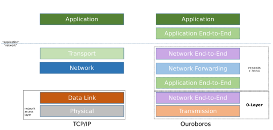
This section provides a high level architectural overview of the prime differences between the Ouroboros model and the 5-Layer Internet model associated with the TCP/IP protocol stack.
Some differences are directly apparent:
- The Transport Layer is replaced with two end-to-end layers, split between the network and the application,
- The Network Layer has two counterparts: the network forwarding layer for unicast and the network flooding layer for broadcast,
- The Data Link Layer is missing altogether,
- The Physical Layer is now called the transmission layer.
Splitting the Transport Layer
The key difference is that functionality that is associated with the Transport Layer (the TCP/UDP protocols) is moved into two independent layers. The application end-to-end layer takes over ARQ and flow control, while the network end-to-end layer is in charge of multiplexing, name-to-address resolution and congestion control. This split of the Transport Layer is actually quite similar to the sublayering (Link Logical Control /Media Access Control) of the Data Link Layer in the Internet Model. The name-to-address resolution functionality (roughly equivalent to DNS SRV resolve) is also inside the end-to-end network layer instead of an (essentially optional) function that the application needs to perform. More specifically, the O7s network IPC API requires only a service name so it can resolve addresses internally, whereas the TCP/IP model Transport Layer needs an IP address and port, leaving it up to the application to resolve the address.
Untangling the Network Layer
The network layer functionality is very similar between O7s and the Internet model. The main difference is that broadcast is split off in the O7s model, and that the network forwarding layer does not hold references to the higher-level layers (so, no 'Protocol' field).
No Data Link Layer
In the Internet model, the Data Link Layer is split up into two sub-layers, called the Link Logical Control (LLC) and Media Access Control (MAC) layers. When looking at the functionality that is associated with these layers, the O7s application end-to-end layer maps directly to link logical control and the O7s network end-to-end layer maps directly to the MAC layer (name-to-address mapping, multiplexing), so there is no need anymore for this layer to be distinct in the O7s model.
Transmission layer instead of Physical Layer
The final change in the model is to abstract the Physical Layer to include (virtual) legacy networks and therefore a more generic 'end of the line' for the model than only a physical medium. The distinct property is that it does not reuse the O7s API and therefore does not interface into the application end-to-end layer. Instead it has functionality that is directly tailored to the specific technology it wraps.
Relation to Location/Identifier split
Loc/Id split starts from the observation that the application is tightly coupled to network (IP) addresses through the Transport Layer via a certain port. This hampers application mobility, as a change in network (IP) address breaks the TCP connection used by the application. Loc/Id split proposes to semantically break up the network layer address into two separate parts, an identifier that is location-independent and specifies the who at the Transport Layer, and a locator that is location-dependent and specifies the where at the network layer. An IPv6 address is 128 bits wide, providing ample material to accommodate this split.
Architecturally, this boils down to a name-to-address resolution step - identifier-to-locator - in a Sub-Layer[1] between the Transport Layer (bound to the identifier) and the Network Layer (using the locator). Changing locator during mobility therefore does not break the Transport Layer connection. While the proposed solution works, the core tenet of Loc/Id split that IP addresses are semantically overloaded[2] is nonsense. The actual problem is a missing (service) name and DNS providing only synonyms for addresses; DNS SRV is a step towards naming applications/services (L5), but DNS/SRV still directly maps these names to the L3 address and L4 port; the application directly binds to the L3/L4 identifiers instead of the L5 name. Both pieces of the puzzle are known, they just need to be put together.
Taken as a whole, Loc/Id split applications perform two lookups: domain name to identifier, and then identifier to locator. This indirection is needed for Loc/Id split to stay compatible with the TCP/IP protocol stack, but it is redundant from the perspective of O7s. It is more efficient to bind applications to service names, and resolve a service name to an address in a single lookup.
The O7s model splits the Transport Layer (see above), adding a service name-to-address resolution mechanism to the network end-to-end layer. The big functional differences with the Sub-Layer proposed in Loc/id and the layers in O7s are that the network end-to-end layer also takes over congestion control and multiplexing from the Transport Layer, and that the remaining functionality - the application end-to-end layer - is considered part of the application.
Relation to Recursive InterNetwork Architecure (RINA)
Main Page: Ouroboros and RINA
The original objective of the Ouroboros prototype was to build a portable user-space implementation of RINA for POSIX systems that could be tailored to embedded devices. As this prototype started off as an implementation of principles outlined by RINA, the Ouroboros model inherits a lot of concepts and terminology from RINA. As such, that's where the credit for those ideas goes. As the prototype evolved, architectural changes were made that further simplified things.
Splitting data transfer control from data transfer
RINA sees the IP fragmentation problem as evidence that the TCP/IP split was incorrect[3]. The solution put forward in RINA is to keep the functionality of TCP and IP in a single logical layer and in a single protocol, called the Error and Flow Control Protocol (EFCP). EFCP is still subdivided in two component protocol (called Data Transfer Protocol (DTP) and Data Transfer Control Protocol (DTCP), but these two protocol share a state vector and are therefore not fully independent.
During the implementation of EFCP in Ouroboros we found that the functionality in EFCP (and thus TCP + IP) could (and therefore should) be split not in 2, but 3 independent layers: the application end-to-end layer, the network end-to-end layer and the network forwarding layer. The IP fragmentation problem is solved by putting the fragmentation bits in the Flow and Retransmission Control Protocol rather than the Data Transfer Protocol and the Flow Allocator reports the path maximum transmission unit (MTU) for a flow as input for the fragmentation function.
O7s Layers vs RINA DIFs
In RINA, DTP and DTCP are in the same Layer. Since end-user programs do not typically perform packet forwarding, there is therefore a hard distinction between 'normal' end-user (distributed) applications and the (distributed) application that is responsible for (reliable) packet transfer. The EFCP protocol provides the necessary functionality for this reliable packet communication between processes, and therefore a process that implements EFCP is called an Inter-Process Communication process (IPCP), a term that originated in Livermore's LINCS network. The distributed application consisting of such IPCPs is called a Distributed IPC Facility (DIF). In contrast, a regular end-user distributed application, consists of distributed application processes (DAPs) and is called a Distributed Application Facility (DAF).
The 3-layer functional split in O7s raised a question for the location of FRCP: should it be part of the DIF, or part of the Application? It was immediately clear that putting it in the application solved some questions that arise with the RINA architecture.
- End-user application multi-homing (i.e. flows over different networks) is still a problem in RINA: only IPCPs can efficiently multi-home. In O7s all processes can effectively multi-home.
- Loss of IPCP state associated with DTCP (sequence numbers, DTCP windows) after crash of an IPCP is not easily recoverable even when the application process survives.
- Reliable flow allocation over a shim-DIF (needed by the IPCP) required a hack for the IPCP to allocate a flows over itself.
- If an IPCP/DIF is needed to provided reliable IPC between two programs, who performs reliable IPC between those programs and the IPCP/DIF? The answer that the OS provides test-and-set is not satisfactory as it requires some (admittedly very reasonable) assumptions outside of the model that are not trivial.
With the application end-to-end layer, the distinction between DIF and DAF is not present in the O7s model. Nevertheless, awaiting more satisfactory terminology O7s still refers to processes making up an O7s Layers as IPCPs, fully aware of the confusion this may cause.
Notes on Layering in O7s
The model as explained above shows Broadcast Layers over Unicast Layers, and Unicast over Unicast Layers. What about the other options?
Unicast over Broadcast
From the perspective of the O7s Layers, the general case of Unicast over Broadcast -- by which we mean that some data packets will be flooded to multiple next-hop IPCPs -- brings with it that Unicast IPCPs would have to be able to identify whether arriving data packets are for them or not. This problem inherently has limited scalability and its utility within O7s is as of yet unclear and requires some further study. In absence of compelling reasons to add this, we currently haven't added this to the general model. This does not imply that a Unicast Layer can not use dedicated Broadcast Layers to implement certain functionalities - an example is routing dissemination in the network forwarding layer.
Since Ethernet does implement unicast over a broadcast domain, we have a dedicated page discussing how Ethernet maps to Ouroboros.
Broadcast over Broadcast
The case where one Broadcast Layer makes use of another Broadcast Layer is also technically feasible. Its utility is also still unclear, which is why it's not currently elaborated on, but allowing this will have little impact on the model.
Mixed and/or combined implementation
Why not merge broadcast and unicast functionality in a single Layer? This is definitely feasible and anyone is free to implement such an IPCP that does both. The net outcome will be a Layer that has a a broadcast network as well as a unicast network at the full scope of that Layer, which may be useful for some particular use cases. However, from a model perspective, Unicast and Broadcast are always two distinct Layers, and mixing the implementation does not alter this fact.
Similarly, a program can be written that implements multiple IPCP modules internally, instead of starting up a process per 'IPCP'.
