diff options
Diffstat (limited to 'content/docs')
| -rw-r--r-- | content/docs/_index.md | 6 | ||||
| -rw-r--r-- | content/docs/compopt.html | 435 | ||||
| -rw-r--r-- | content/docs/development/_index.md | 6 | ||||
| -rw-r--r-- | content/docs/documentation.md | 41 | ||||
| -rw-r--r-- | content/docs/elements.md | 98 | ||||
| -rw-r--r-- | content/docs/faq.md | 122 | ||||
| -rw-r--r-- | content/docs/irmd.md | 90 | ||||
| -rw-r--r-- | content/docs/manuals.md | 18 | ||||
| -rw-r--r-- | content/docs/performance.md | 74 | ||||
| -rw-r--r-- | content/docs/protocols.md | 116 | ||||
| -rw-r--r-- | content/docs/quickstart.md | 11 | ||||
| -rw-r--r-- | content/docs/tutorials/_index.md | 5 | ||||
| -rw-r--r-- | content/docs/tutorials/dev-tut-1.md | 73 | ||||
| -rw-r--r-- | content/docs/tutorials/ovpn-tut.md | 217 | ||||
| -rw-r--r-- | content/docs/tutorials/tutorial-1.md | 153 | ||||
| -rw-r--r-- | content/docs/tutorials/tutorial-2.md | 298 | ||||
| -rw-r--r-- | content/docs/tutorials/tutorial-3.md | 210 | ||||
| -rw-r--r-- | content/docs/tutorials/tutorial-4.md | 123 | ||||
| -rw-r--r-- | content/docs/what.md | 152 |
19 files changed, 0 insertions, 2248 deletions
diff --git a/content/docs/_index.md b/content/docs/_index.md deleted file mode 100644 index f2a842a..0000000 --- a/content/docs/_index.md +++ /dev/null @@ -1,6 +0,0 @@ ---- -title: Documentation -date: 2019-06-22 -type: page -draft: false ---- diff --git a/content/docs/compopt.html b/content/docs/compopt.html deleted file mode 100644 index 4c4459c..0000000 --- a/content/docs/compopt.html +++ /dev/null @@ -1,435 +0,0 @@ ---- -title: "Compilation options" -date: 2019-06-22 -draft: false ---- - -<p> - Below is a list of the compile-time configuration options for - Ouroboros. These can be set using -</p> -<pre><code>$ cmake -D<option>=<value> ..</code></pre> -<p>or using</p> -<pre><code>ccmake .</code></pre> -<p> - Options will only show up in ccmake if they are relevant for - your system configuration. The default value for each option - is <u>underlined</u>. Boolean values will print as ON/OFF in - ccmake instead of True/False. -</p> -<table> - <tr> - <th>Option</th> - <th>Description</th> - <th>Values</th> - </tr> - <tr> - <th colspan="3">Compilation options</th> - </tr> - <tr> - <td>CMAKE_BUILD_TYPE</td> - <td> - Set the build type for Ouroboros. Debug builds will add some - extra logging. The debug build can further enable the - address sanitizer (ASan) thread sanitizer (TSan) and leak - sanitizer (LSan) options. - </td> - <td> - <u>Release</u>, Debug, DebugASan, DebugTSan, DebugLSan - </td> - </tr> - <tr> - <td>CMAKE_INSTALL_PREFIX</td> - <td> - Set a path prefix in order to install Ouroboros in a - sandboxed environment. Default is a system-wide install. - </td> - <td> - <path> - </td> - </tr> - <tr> - <td>DISABLE_SWIG</td> - <td> - Disable SWIG support. - </td> - <td> - True, <u>False</u> - </td> - </tr> - <tr> - <th colspan="3">Library options</th> - <tr> - <tr> - <td>DISABLE_FUSE</td> - <td> - Disable FUSE support, removing the virtual filesystem under - <FUSE_PREFIX>. - </td> - <td> - True, <u>False</u> - </td> - </tr> - <tr> - <td>FUSE_PREFIX</td> - <td> - Set the path where the fuse system should be - mounted. Default is /tmp/ouroboros. - </td> - <td> - <path> - </td> - </tr> - <tr> - <td>DISABLE_LIBGCRYPT</td> - <td> - Disable support for using the libgcrypt library for - cryptographically secure random number generation and - hashing. - </td> - <td> - True, <u>False</u> - </td> - </tr> - <tr> - <td>DISABLE_OPENSSL</td> - <td> - Disable support for the libssl library for cryptographic - random number generation and hashing. - </td> - <td> - True, <u>False</u> - </td> - </tr> - <tr> - <td>DISABLE_ROBUST_MUTEXES</td> - <td> - Disable - <a href="http://pubs.opengroup.org/onlinepubs/9699919799/functions/pthread_mutexattr_getrobust.html"> - robust mutex - </a> - support. Without robust mutex support, Ouroboros may lock up - if processes are killed using SIGKILL. - </td> - <td> - True, <u>False</u> - </td> - </tr> - <tr> - <td>PTHREAD_COND_CLOCK</td> - <td> - Set the - <a href="http://pubs.opengroup.org/onlinepubs/9699919799/basedefs/time.h.html"> - clock type - </a> - to use for timeouts for pthread condition variables. Default - on Linux/FreeBSD: CLOCK_MONOTONIC. Default on OS X: - CLOCK_REALTIME. - </td> - <td> - <clock_id_t> - </td> - </tr> - <tr> - <th colspan="3">Shared memory system options</th> - <tr> - <tr> - <td>SHM_PREFIX</td> - <td> - Set a prefix for the shared memory filenames. The mandatory - leading - <a href="http://pubs.opengroup.org/onlinepubs/9699919799/functions/shm_open.html"> - slash - </a> - is added by the build system. Default is "ouroboros". - </td> - <td> - <size_t> - </td> - </tr> - <tr> - <td>SHM_BUFFER_SIZE</td> - <td> - Set the maximum total number of packet blocks Ouroboros - can buffer at any point in time. Must be a power of 2. - </td> - <td> - <size_t> - </td> - </tr> - <tr> - <td>SHM_RDRB_BLOCK_SIZE</td> - <td> - Set the size of a packet block. Default: page size of the - system. - </td> - <td> - <size_t> - </td> - </tr> - <tr> - <td>SHM_RDRB_MULTI-BLOCK</td> - <td> - Allow packets that are larger than a single packet block. - </td> - <td> - <u>True</u>, False - </td> - </tr> - <tr> - <td>DU_BUFF_HEADSPACE</td> - <td> - Set the amount of space to allow for the addition of - protocol headers when a new packet buffer is passed to the - system. Default: 128 bytes. - </td> - <td> - <size_t> - </td> - </tr> - <tr> - <td>DU_BUFF_TAILSPACE</td> - <td> - Set the amount of space to allow for the addition of - protocol tail information (CRCs) when a new packet buffer - is passed to the system. Default: 32 bytes. - </td> - <td> - <size_t> - </td> - </tr> - <tr> - <th colspan="3">IRMd options</th> - </tr> - <tr> - <td>SYS_MAX_FLOWS</td> - <td> - The maximum number of flows this Ouroboros system can - allocate. Default: 10240. - </td> - <td> - <size_t> - </td> - </tr> - <tr> - <td>SOCKET_TIMEOUT</td> - <td> - The IRMd sends commands to IPCPs over UNIX sockets. This - sets the timeout for such commands in milliseconds. Some - commands can be set independently. Default: 1000. - </td> - <td> - <time_t> - </td> - </tr> - <tr> - <td>BOOTSTRAP_TIMEOUT</td> - <td> - Timeout for the IRMd to wait for a response to a bootstrap - command from an IPCP in milliseconds. Default: 5000. - </td> - <td> - <time_t> - </td> - </tr> - <tr> - <td>ENROLL_TIMEOUT</td> - <td> - Timeout for the IRMd to wait for a response to an enroll - command from an IPCP in milliseconds. Default: 60000. - </td> - <td> - <time_t> - </td> - </tr> - <tr> - <td>CONNECT_TIMEOUT</td> - <td> - Timeout for the IRMd to wait for a response to a connect - command from an IPCP in milliseconds. Default: 5000. - </td> - <td> - <time_t> - </td> - </tr> - <tr> - <td>REG_TIMEOUT</td> - <td> - Timeout for the IRMd to wait for a response to a register - command from an IPCP in milliseconds. Default: 3000. - </td> - <td> - <time_t> - </td> - </tr> - <tr> - <td>QUERY_TIMEOUT</td> - <td> - Timeout for the IRMd to wait for a response to a query - command from an IPCP in milliseconds. Default: 3000. - </td> - <td> - <time_t> - </td> - </tr> - <tr> - <td>IRMD_MIN_THREADS</td> - <td> - The minimum number of threads in the threadpool the IRMd - keeps waiting for commands. Default: 8. - </td> - <td> - <size_t> - </td> - </tr> - <tr> - <td>IRMD_ADD_THREADS</td> - <td> - The number of threads the IRMd will create if the current - available threadpool is lower than - IRMD_MIN_THREADS. Default: 8. - </td> - <td> - <size_t> - </td> - </tr> - <tr> - <th colspan="3">IPCP options</th> - </tr> - <tr> - <td>DISABLE_RAPTOR</td> - <td> - Disable support for the raptor NetFPGA implementation. - </td> - <td> - True, <u>False</u> - </td> - </tr> - <tr> - <td>DISABLE_BPF</td> - <td> - Disable support for the Berkeley Packet Filter device - interface for the Ethernet LLC layer. If no suitable - interface is found, the LLC layer will not be built. - </td> - <td> - True, <u>False</u> - </td> - </tr> - <tr> - <td>DISABLE_NETMAP</td> - <td> - Disable <a href="http://info.iet.unipi.it/~luigi/netmap/">netmap</a> - support for the Ethernet LLC layer. If no suitable interface - is found, the LLC layer will not be built. - </td> - <td> - True, <u>False</u> - </td> - </tr> - <tr> - <td>DISABLE_RAW_SOCKETS</td> - <td> - Disable raw sockets support for the Ethernet LLC layer. If - no suitable interface is found,the LLC layer will not be - built. - </td> - <td> - True, <u>False</u> - </td> - </tr> - <tr> - <td>DISABLE_DDNS</td> - <td> - Disable Dynamic Domain Name System support for the UDP - layer. - </td> - <td> - True, <u>False</u> - </td> - </tr> - <tr> - <td>IPCP_SCHED_THR_MUL</td> - <td> - The number of scheduler threads an IPCP runs per QoS - cube. Default is 2. - </td> - <td> - <size_t> - </td> - </tr> - <tr> - <td>IPCP_QOS_CUBE_BE_PRIORITY</td> - <td> - Priority for the best effort qos cube scheduler - thread. This is mapped to a system value. Scheduler - threads have at least half the system max priority value. - </td> - <td> - <u>0</u>..99 - </td> - </tr> - <tr> - <td>IPCP_QOS_CUBE_VIDEO_PRIORITY</td> - <td> - Priority for the video qos cube scheduler thread. This is - mapped to a system value. Scheduler threads have at least - half the system max priority value. - </td> - <td> - 0..<u>90</u>..99 - </td> - </tr> - <tr> - <td>IPCP_QOS_CUBE_VOICE_PRIORITY</td> - <td> - Priority for the voice qos cube scheduler thread. This is - mapped to a system value. Scheduler threads have at least - half the system max priority value. - </td> - <td> - 0..<u>99</u> - </td> - </tr> - <tr> - <td>IPCP_FLOW_STATS</td> - <td> - Enable statistics for the data transfer component. - </td> - <td> - True, <u>False</u> - </td> - </tr> - - <tr> - <td>PFT_SIZE</td> - <td> - The forwarding table in the normal IPCP uses a - hashtable. This sets the size of this hash table. Default: 4096. - </td> - <td> - <size_t> - </td> - </tr> - <tr> - <td>IPCP_MIN_THREADS</td> - <td> - The minimum number of threads in the threadpool the IPCP - keeps waiting for commands. Default: 4. - </td> - <td> - <size_t> - </td> - </tr> - <tr> - <td>IPCP_ADD_THREADS</td> - <td> - The number of threads the IPCP will create if the current - available threadpool is lower than - IPCP_MIN_THREADS. Default:4. - </td> - <td> - <size_t> - </td> - </tr> -</table> diff --git a/content/docs/development/_index.md b/content/docs/development/_index.md deleted file mode 100644 index 0a5257f..0000000 --- a/content/docs/development/_index.md +++ /dev/null @@ -1,6 +0,0 @@ ---- -title: Development -date: 2019-06-22 -#description: Ouroboros development blog -draft: false ---- diff --git a/content/docs/documentation.md b/content/docs/documentation.md deleted file mode 100644 index f48e03c..0000000 --- a/content/docs/documentation.md +++ /dev/null @@ -1,41 +0,0 @@ ---- -title: "Documentation" -date: 2019-06-22 -type: page -draft: false ---- - -# Getting started - -* [Requirements](/requirements/) -* [Download Ouroboros](/download/) -* [Installing Ouroboros](/install/) -* [Compilation options](/compopt/) - -# User tutorials - -These tutorials will be kept up-to-date for the latest version of -Ouroboros. Check the version that is installed on your system using: - -``` -$ irmd --version -``` - -The output shown in the tutorials uses a [*debug*](/compopt) build -of Ouroboros, with FUSE installed and IPCP\_FLOW\_STATS enabled to show -some additional details of what is happening. - -* [Tutorial 1: Local test](/tutorial-1/) -* [Tutorial 2: Adding a layer](/tutorial-2/) -* [Tutorial 3: IPCP statistics](/tutorial-3/) -* [Tutorial 4: Connecting two machines over Ethernet](/tutorial-4/) - -# Developer tutorials - -* [Developer tutorial 1: Writing your first Ouroboros C program](/dev-tut-1/) - -# Extra info - -* [Manual pages](/manuals/) -* [Frequently Asked Questions (FAQ)](/faq/) -* [Performance tests](/performance/) diff --git a/content/docs/elements.md b/content/docs/elements.md deleted file mode 100644 index e84bcfc..0000000 --- a/content/docs/elements.md +++ /dev/null @@ -1,98 +0,0 @@ ---- -title: "Elements of a recursive network" -author: "Dimitri Staessens" -description: "what" -date: 2019-07-11 -#type: page -draft: false ---- - -This section describes the high-level concepts and building blocks are -used to construct a decentralized [recursive network](/docs/what): -layers and flows. (Ouroboros has two different kinds of layers, but -we will dig into all the fine details in later posts). - -A __layer__ in a recursive network embodies all of the functionalities -that are currently in layers 3 and 4 of the OSI model (along with some -other functions). The difference is subtle and takes a while to get -used to (not unlike the differences in the term *variable* in -imperative versus functional programming languages). A recursive -network layer handles requests for communication to some remote -process and, as a result, it either provides a handle to a -communication channel -- a __flow__ endpoint --, or it raises some -error that no such flow could be provided. - -A layer in Ouroboros is built up from a bunch of (identical) programs -that work together, called Inter-Process Communication (IPC) Processes -(__IPCPs__). The name "IPCP" was first coined for a component of the -[LINCS] -(https://www.osti.gov/biblio/5542785-delta-protocol-specification-working-draft) -hierarchical network architecture built at Lawrence Livermore National -Laboratories and was taken over in the RINA architecture. These IPCPs -implement the core functionalities (such as routing, a dictionary) and -can be seen as small virtual routers for the recursive network. - -<center> {{<figure class="w-200" src="/images/rec_netw.jpg">}} </center> - -In the illustration, a small 5-node recursive network is shown. It -consists of two hosts that connect via edge routers to a small core. -There are 6 layers in this network, labelled __A__ to __F__. - -On the right-hand end-host, a server program __Y__ is running (think a -mail server program), and the (mail) client __X__ establishes a flow -to __Y__ over layer __F__ (only the endpoints are drawn to avoid -cluttering the image). - -Now, how does the layer __F__ get the messages from __X__ to __Y__? -There are 4 IPCPs (__F1__ to __F4__) in layer __F__, that work -together to provide the flow between the applications __X__ and -__Y__. And how does __F3__ get the info to __F4__? That is where the -recursion comes in. A layer at some level (its __rank__), will use -flows from another layer at a lower level. The rank of a layer is a -local value. In the hosts, layer __F__ is at rank 1, just above layer -__C__ or layer __E_. In the edge router, layer __F__ is at rank 2, -because there is also layer __D__ in that router. So the flow between -__X__ and __Y__ is supported by flows in layer __C__, __D__ and __E__, -and the flows in layer __D__ are supported by flows in layers __A__ -and __B__. - -Of course these dependencies can't go on forever. At the lowest level, -layers __A__, __B__, __C__ and __E__ don't depend on a lower layer -anymore, and are sometimes called 0-layers. They only implement the -functions to provide flows, but internally, they are specifically -tailored to a transmission technology or a legacy network -technology. Ouroboros supports such layers over (local) shared memory, -over the User Datagram Protocol, over Ethernet and a prototype that -supports flows over an Ethernet FPGA device. This allows Ouroboros to -integrate with existing networks at OSI layers 4, 2 and 1. - -If we then complete the picture above, when __X__ sends a packet to -__Y__, it passes it to __F3__, which uses a flow to __F1__ that is -implemented as a direct flow between __C2__ and __C1__. __F1__ then -forwards the packet to __F2__ over a flow that is supported by layer -__D__. This flow is implemented by two flows, one from __D2__ to -__D1__, which is supported by layer A, and one from __D1__ to __D3__, -which is supported by layer __B__. __F2__ will forward the packet to -__F4__, using a flow provided by layer __E__, and __F4__ then delivers -the packet to __Y__. So the packet moves along the following chain of -IPCPs: __F3__ --> __C2__ --> __C1__ --> __F1__ --> __D2__ --> __A1__ ---> __A2__ --> __D1__ --> __B1__ --> __B2__ --> __D3__ --> __F2__ --> -__E1__ --> __E2__ --> __F4__. - -<center> {{<figure class="w-200" src="/images/dependencies.jpg">}} </center> - -A recursive network has __dependencies__ between layers in the -network, and between IPCPs in a __system__. These dependencies can be -represented as a directed acyclic graph (DAG). To avoid problems, -these dependencies should never contain cycles (so a layer I should -not directly or indirectly depend on itself). The rank of a layer is -defined (either locally or globally) as the maximum depth of this -layer in the DAG. - -[Next: Creating layers](/docs/irmd/) - ---- -Changelog: - -2019 07 11: Initial version.<br> -2019 07 23: Added dependency graph figure diff --git a/content/docs/faq.md b/content/docs/faq.md deleted file mode 100644 index b3ac687..0000000 --- a/content/docs/faq.md +++ /dev/null @@ -1,122 +0,0 @@ ---- -title: "Frequently Asked Questions (FAQ)" -date: 2019-06-22 -draft: false ---- - -Got a question that is not listed here? Just pop it on our IRC channel -or mailing list and we will be happy to answer it! - -[What is Ouroboros?](#what)\ -[Is Ouroboros the same as the Recursive InterNetwork Architecture -(RINA)?](#rina)\ -[How can I use Ouroboros right now?](#deploy)\ -[What are the benefits of Ouroboros?](#benefits)\ -[How do you manage the namespaces?](#namespaces)\ - -### <a name="what">What is Ouroboros?</a> - -Ouroboros is a packet-based IPC mechanism. It allows programs to -communicate by sending messages, and provides a very simple API to do -so. At its core, it's an implementation of a recursive network -architecture. It can run next to, or over, common network technologies -such as Ethernet and IP. - -[[back to top](#top)] - -### <a name="rina">Is Ouroboros the same as the Recursive InterNetwork Architecture (RINA)?</a> - -No. Ouroboros is a recursive network, and is born as part of our -research into RINA networks. Without the pioneering work of John Day and -others on RINA, Ouroboros would not exist. We consider the RINA model an -elegant way to think about distributed applications and networks. - -However, there are major architectural differences between Ouroboros and -RINA. The most important difference is the location of the "transport -functions" which are related to connection management, such as -fragmentation, packet ordering and automated repeat request (ARQ). RINA -places these functions in special applications called IPCPs that form -layers known as Distributed IPC Facilities (DIFs) as part of a protocol -called EFCP. This allows a RINA DIF to provide an *IPC service* to the -layer on top. - -Ouroboros has those functions in *every* application. The benefit of -this approach is that it is possible to multi-home applications in -different networks, and still have a reliable connection. It is also -more resilient since every connection is - at least in theory - -recoverable unless the application itself crashes. So, Ouroboros IPCPs -form a layer that only provides *IPC resources*. The application does -its connection management, which is implemented in the Ouroboros -library. This architectural difference impact the components and -protocols that underly the network, which are all different from RINA. - -This change has a major impact on other components and protocols. We are -preparing a research paper on Ouroboros that will contain all these -details and more. - -[[back to top](#top)] - -### <a name="deploy">How can I use Ouroboros right now?</a> - -At this point, Ouroboros is a useable prototype. You can use it to build -small deployments for personal use. There is no global Ouroboros network -yet, but if you're interested in helping us set that up, contact us on -our channel or mailing list. - -[[back to top](#top)] - -### <a name="benefits">What are the benefits of Ouroboros?</a> - -We get this question a lot, and there is no single simple answer to -it. Its benefits are those of a RINA network and more. In general, if -two systems provide the same service, simpler systems tend to be the -more robust and reliable ones. This is why we designed Ouroboros the -way we did. It has a bunch of small improvements over current networks -which may not look like anything game-changing by themselves, but do -add up. The reaction we usually get when demonstrating Ouroboros, is -that it makes everything really really easy. - -Some benefits are improved anonymity as we do not send source addresses -in our data transfer packets. This also prevents all kinds of swerve and -amplification attacks. The packet structures are not fixed (as the -number of layers is not fixed), so there is no fast way to decode a -packet when captured "raw" on the wire. It also makes Deep Packet -Inspection harder to do. By attaching names to data transfer components -(so there can be multiple of these to form an "address"), we can -significantly reduce routing table sizes. - -The API is very simple and universal, so we can run applications as -close to the hardware as possible to reduce latency. Currently it -requires quite some work from the application programmer to create -programs that run directly over Ethernet or over UDP or over TCP. With -the Ouroboros API, the application doesn't need to be changed. Even if -somebody comes up with a different transmission technology, the -application will never need to be modified to run over it. - -Ouroboros also makes it easy to run different instances of the same -application on the same server and load-balance them. In IP networks -this requires at least some NAT trickery (since each application is tied -to an interface:port). For instance, it takes no effort at all to run -three different webserver implementations and load-balance flows between -them for resiliency and seamless attack mitigation. - -The architecture still needs to be evaluated at scale. Ultimately, the -only way to get the numbers, are to get a large (pre-)production -deployment with real users. - -[[back to top](#top)] - -### <a name="namespaces">How do you manage the namespaces?</a> - -Ouroboros uses names that are attached to programs and processes. The -layer API always uses hashes and the network maps hashes to addresses -for location. This function is similar to a DNS lookup. The current -implementation uses a DHT for that function in the ipcp-normal (the -ipcp-udp uses a DynDNS server, the eth-llc and eth-dix use a local -database with broadcast queries). - -But this leaves the question how we assign names. Currently this is -ad-hoc, but eventually we will need an organized way for a global -namespace so that application names are unique. If we want to avoid a -central authority like ICANN, a distributed ledger would be a viable -technology to implement this, similar to, for instance, namecoin. diff --git a/content/docs/irmd.md b/content/docs/irmd.md deleted file mode 100644 index f6b60bd..0000000 --- a/content/docs/irmd.md +++ /dev/null @@ -1,90 +0,0 @@ ---- -title: "Creating layers" -author: "Dimitri Staessens" -description: "IRMd" -date: 2019-07-23 -#type: page -draft: false ---- - -The most important structure in recursive networks are the layers, -that are built op from [elements](/docs/elements/) called -Inter-Process Communication Processes (IPCPs). (Note again that the -layers in recursive networks are not the same as layers in the OSI -model). - -<center> -{{<figure class="fl w-90" - src="/images/creating_layers.jpg">}} -</center> - -Now, the question is, how do we build these up these layers? IPCPs are -small programs (think of small virtual routers) that need to be -started, configured and managed. This functionality is usually -implemented in some sort of management daemon. Current RINA -implementations call it the *IPC manager*, Ouroboros calls it the -__IPC Resource Management daemon__ or __IRMd__ for short. The IRMd -lies at the heart of each system that is participating in an Ouroboros -network, implementing the core function primitives. It serves as the -entry point for the system/network administrator to manage the network -resources. - -We will describe the functions of the Ouroboros IRMd with the -Ouroboros commands for illustration and to make things a bit more -tangible. - -The first set of primitives, __create__ (and __destroy__), allow -creating IPCPs of a given *type*. This just runs the process without -any further configuration. At this point, that process is not part of -any layer. - -``` -$ irm ipcp create type unicast name my_ipcp -$ irm ipcp list -+---------+----------------------+------------+----------------------+ -| pid | name | type | layer | -+---------+----------------------+------------+----------------------+ -| 7224 | my_ipcp | unicast | Not enrolled | -+---------+----------------------+------------+----------------------+ -``` - -The example above creates a unicast IPCP and gives that IPCP a name -(we called it "my_ipcp"). A listing of the IPCPs in the system shows -that the IPCP is running as process 7224, and it is not part of a -layer ("*Not enrolled*"). - -To create a new functioning network layer, we need to configure the -IPCP, using a primitive called __bootstrapping__. Bootstrapping sets a -number of configuration optionss for the layer (such as the routing -algorithm to use) and activates the IPCP to allow it to start -providing flows. The Ouroboros command line allows creating an IPCP -with some default values, that are a bit like a vanilla IPv4 network: -32-bit addresses and shortest-path link-state routing. - -``` -$ irm ipcp bootstrap name my_ipcp layer my_layer -$ irm ipcp list -+---------+----------------------+------------+----------------------+ -| pid | name | type | layer | -+---------+----------------------+------------+----------------------+ -| 7224 | my_ipcp | unicast | my_layer | -+---------+----------------------+------------+----------------------+ -``` - -Now we have a single node-network. In order to create a larger -network, we connect and configure new IPCPs using a third primitive -called __enrollment__. When enrolling an IPCP in a network, it will -create a flow (using a lower layer) to an existing member of the -layer, download the bootstrapping information, and use it to configure -itself as part of this layer. - -The final primitive is the __connect__ (and __disconnect__) -primitive. This allows to create *adjacencies* between network nodes. - -An example of how to create a small two-node network is given in -[tutorial 2](/docs/tutorials/tutorial-2/) - ---- -Changelog: - -2019-07-23: Initial version diff --git a/content/docs/manuals.md b/content/docs/manuals.md deleted file mode 100644 index 4ce3bce..0000000 --- a/content/docs/manuals.md +++ /dev/null @@ -1,18 +0,0 @@ ---- -title: "Manuals" -date: 2019-06-22 -draft: false ---- - -These are the man pages for ouroboros. If ouroboros is installed on your -system, you can also access them using "man". - -For general use of Ouroboros, refer to the [Ouroboros User -Manual](/man/man8/ouroboros.8.html). - -For use of the API, refer to the [Ouroboros Programmer's -Manual](/man/man3/flow_alloc.3.html). - -The man section also contains a -[tutorial](man/man7/ouroboros-tutorial.7.html) and a -[glossary](man/man7/ouroboros-glossary.7.html). diff --git a/content/docs/performance.md b/content/docs/performance.md deleted file mode 100644 index 5cd2dc0..0000000 --- a/content/docs/performance.md +++ /dev/null @@ -1,74 +0,0 @@ ---- -title: "Performance tests" -date: 2019-06-22 -draft: false ---- - -Below you will find some measurements on the performance of Ouroboros. - -### Local IPC performance test - -This test uses the *oping* tool to measure round trip time. This tools -generates traffic from a single thread. The server has a single thread -that handles ping requests and sends responses. - -``` -$ oping -n oping -i 0 -s <sdu size> -``` - -The figure below shows the round-trip-time (rtt) in milliseconds (ms) -for IPC over a local layer for different packet sizes, measured on an -Intel Core i7 4500U (2 cores @ 2.4GHz). For small payloads (up to 1500 -bytes), the rtt is quite stable at around 30 µs. This will mostly depend -on CPU frequency and to a lesser extent the OS scheduler. - -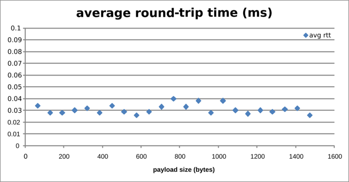 - -This test uses the *ocbr* tool to measure goodput between a sender and -receiver. The sender generates traffic from a single thread. The -receiver handles traffic from a single thread. The performance will -heavily depend on your system's memory layout (cache sizes etc). This -test was run on a Dell XPS13 9333 (2013 model). - -``` -$ ocbr -n ocbr -f -s <sdu size> -``` - -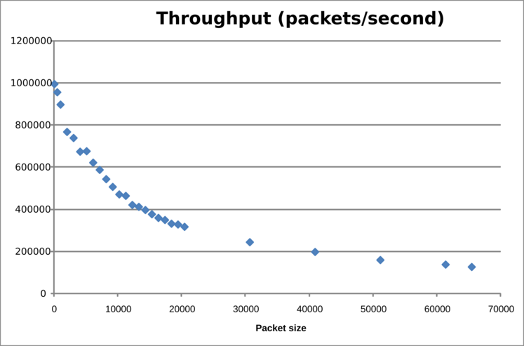 - -The goodput (Mb/s) is shown below: - -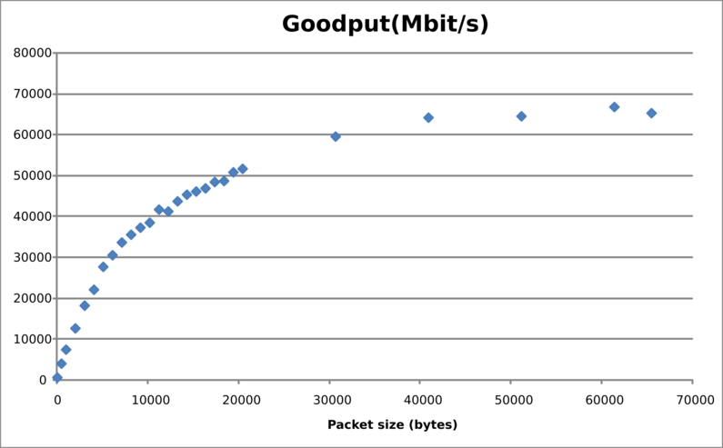 - -### Ethernet + Normal test - -This connects 2 machines over a Gb LAN using the eth-dix and a normal -layer. The oping server is registered in the dix as oping.dix and in the -normal as oping.normal. The machines (dual-socket Intel Xeon E5520) are -connected over a non-blocking switch. - -Latency test: - -ICMP ping: - -``` ---- 192.168.1.2 ping statistics --- -1000 packets transmitted, 1000 received, 0% packet loss, time 65ms -rtt min/avg/max/mdev = 0.046/0.049/0.083/0.002 ms, ipg/ewma 0.065/0.049 ms -``` - -oping over eth-dix: - -``` ---- oping.dix ping statistics --- -1000 SDUs transmitted, 1000 received, 0% packet loss, time: 66.142 ms -rtt min/avg/max/mdev = 0.098/0.112/0.290/0.010 ms -``` - -oping over eth-normal: - -``` ---- oping.normal ping statistics --- -1000 SDUs transmitted, 1000 received, 0% packet loss, time: 71.532 ms -rtt min/avg/max/mdev = 0.143/0.180/0.373/0.020 ms -```
\ No newline at end of file diff --git a/content/docs/protocols.md b/content/docs/protocols.md deleted file mode 100644 index 571ba98..0000000 --- a/content/docs/protocols.md +++ /dev/null @@ -1,116 +0,0 @@ ---- -title: "Ouroboros packet network protocols" -author: "Dimitri Staessens" -description: "protocols" -date: 2019-09-06 -#type: page -draft: false ---- - -# Network protocol - -As Ouroboros tries to preserve privacy as much as possible, it has an -*absolutely minimal network protocol*: - -``` - 0 1 2 3 - 0 1 2 3 4 5 6 7 8 9 0 1 2 3 4 5 6 7 8 9 0 1 2 3 4 5 6 7 8 9 0 1 - +-+-+-+-+-+-+-+-+-+-+-+-+-+-+-+-+-+-+-+-+-+-+-+-+-+-+-+-+-+-+-+-+ - | | - + Destination Address + - | | - +-+-+-+-+-+-+-+-+-+-+-+-+-+-+-+-+-+-+-+-+-+-+-+-+-+-+-+-+-+-+-+-+ - | Time-to-Live | QoS | ECN | EID | - +-+-+-+-+-+-+-+-+-+-+-+-+-+-+-+-+-+-+-+-+-+-+-+-+-+-+-+-+-+-+-+-+ - | EID | - +-+-+-+-+-+-+-+-+ -``` - -The 5 fields in the Ouroboros network protocol are: - -* Destination address: This specifies the address to forward the - packet to. The width of this field is configurable based on various - preferences and the size of the envisioned network. The Ouroboros - default is 64 bits. Note that there is _no source address_, this is - agreed upon during _flow allocation_. - -* Time-to-Live: Similar to IPv4 and IPv6 (where this field is called - Hop Limit), this ensures that packets don't get forwarded forever in - the network, for instance due to (transient) loops in the forwarding - path. The Ouroboros default for the width is one octet (byte). - -* QoS: Ouroboros supports Quality of Service via a number of methods - (out of scope for this page), and this field is used to prioritize - scheduling of the packets when forwarding. For instance, if the - network gets congested and queues start filling up, higher priority - packets (e.g. a voice call) get scheduled more often than lower - priority packets (e.g. a file download). By default this field takes - one octet. - -* ECN: This field specifies Explicit Congestion Notification (ECN), - with similar intent as the ECN bits in the Type-of-Service field in - IPv4 / Traffic Class field in IPv6. The Ouroboros ECN field is by - default one octet wide, and its value is set to an increasing value - as packets are queued deeper and deeper in a congested routers' - forwarding queues. Ouroboros enforces Forward ECN (FECN). - -* EID: The Endpoint Identifier (EID) field specified the endpoint for - which to deliver the packet. The width of this field is configurable - (the figure shows 16 bits). The values of this field is chosen by - the endpoints, usually at _flow allocation_. It can be thought of as - similar to an ephemeral port. However, in Ouroboros there is no - hardcoded or standardized mapping of an EID to an application. - -# Transport protocol - -Packet switched networks use transport protocols on top of their -network protocol in order to deal with lost or corrupted packets. - -The Ouroboros Transport protocol (called the _Flow and Retransmission -Control Protocol_, FRCP) has only 4 fields: - -``` - 0 1 2 3 - 0 1 2 3 4 5 6 7 8 9 0 1 2 3 4 5 6 7 8 9 0 1 2 3 4 5 6 7 8 9 0 1 - +-+-+-+-+-+-+-+-+-+-+-+-+-+-+-+-+-+-+-+-+-+-+-+-+-+-+-+-+-+-+-+-+ - | Flags | Window | - +-+-+-+-+-+-+-+-+-+-+-+-+-+-+-+-+-+-+-+-+-+-+-+-+-+-+-+-+-+-+-+-+ - | Sequence Number | - +-+-+-+-+-+-+-+-+-+-+-+-+-+-+-+-+-+-+-+-+-+-+-+-+-+-+-+-+-+-+-+-+ - | Acknowledgment Number | - +-+-+-+-+-+-+-+-+-+-+-+-+-+-+-+-+-+-+-+-+-+-+-+-+-+-+-+-+-+-+-+-+ - -``` - -* Flags: There are 7 flags defined for FRCP. - - - DATA: Indicates that the packet is carrying data (allows for 0 - length data). - - - DRF : Data Run Flag, indicates that there are no unacknowledged - packets in flight for this connection. - - - ACK : Indicates that this packet carries an acknowledgment. - - FC : Indicates that this packet updates the flow control window. - - RDVZ: Rendez-vous, this is used to break a zero-window deadlock - that can arise when an update to the flow control window - gets lost. RDVZ packets must be ACK'd. - - FFGM: First Fragment, this packet contains the first fragment of - a fragmented payload. - - MFGM: More Fragments, this packet is not the last fragment of a - fragmented payload. - -* Window: This updates the flow control window. - -* Sequence Number: This is a monotonically increasing sequence number - used to (re)order the packets at the receiver. - -* Acknowledgment Number: This is set by the receiver to indicate the - highest sequence number that was received in - order. - ---- -Changelog: - -2019 09 05: Initial version.<br> -2019 09 06: Added section on transport protocol.
\ No newline at end of file diff --git a/content/docs/quickstart.md b/content/docs/quickstart.md deleted file mode 100644 index a1bb44b..0000000 --- a/content/docs/quickstart.md +++ /dev/null @@ -1,11 +0,0 @@ ---- -title: "Quick Start" -linktitle: "Quick Start" -date: 2019-06-22 -type: page -draft: false -description: "Quick Start Guide" ---- - - -This quickstart guide is under construction.
\ No newline at end of file diff --git a/content/docs/tutorials/_index.md b/content/docs/tutorials/_index.md deleted file mode 100644 index b35d0b8..0000000 --- a/content/docs/tutorials/_index.md +++ /dev/null @@ -1,5 +0,0 @@ ---- -title: "Ouroboros Tutorials" -date: 2019-06-22 -draft: false ----
\ No newline at end of file diff --git a/content/docs/tutorials/dev-tut-1.md b/content/docs/tutorials/dev-tut-1.md deleted file mode 100644 index ceac8b6..0000000 --- a/content/docs/tutorials/dev-tut-1.md +++ /dev/null @@ -1,73 +0,0 @@ ---- -title: "Developer tutorial 1: Writing your first Ouroboros C program" -draft: false ---- - -This tutorial will guide you to write your first ouroboros program. It -will use the basic Ouroboros IPC Application Programming Interface. It -will has a client and a server that send a small message from the client -to the server. - -We will explain how to connect two applications. The server application -uses the flow_accept() call to accept incoming connections and the -client uses the flow_alloc() call to connect to the server. The -flow_accept and flow_alloc call have the following definitions: - -``` -int flow_accept(qosspec_t * qs, const struct timespec * timeo); -int flow_alloc(const char * dst, qosspec_t * qs, const struct -timespec * timeo); -``` - -On the server side, the flow_accept() call is a blocking call that will -wait for an incoming flow from a client. On the client side, the -flow_alloc() call is a blocking call that allocates a flow to *dst*. -Both calls return an non-negative integer number describing a "flow -descriptor", which is very similar to a file descriptor. On error, they -will return a negative error code. (See the [man -page](/man/man3/flow_alloc.html) for all details). If the *timeo* -parameter supplied is NULL, the calls will block indefinitely, otherwise -flow_alloc() will return -ETIMEDOUT when the time interval provided by -*timeo* expires. We are working on implementing non-blocking versions if -the provided *timeo* is 0. - -After the flow is allocated, the flow_read() and flow_write() calls -are used to read from the flow descriptor. They operate just like the -read() and write() POSIX calls. The default behaviour is that these -calls will block. To release the resource, the flow can be deallocated -using flow_dealloc. - -``` -ssize_t flow_write(int fd, const void * buf, size_t count); -ssize_t flow_read(int fd, void * buf, size_t count); int -flow_dealloc(int fd); -``` - -So a very simple application would just need a couple of lines of code -for both the server and the client: - -``` -/* server side */ -char msg[BUF_LEN]; -int fd = flow_accept(NULL, NULL); -flow_read(fd, msg, BUF_LEN); -flow_dealloc(fd); - -/* client side */ -char * msg = "message"; -int fd = flow_alloc("server", NULL, NULL); -flow_write(fd, msg, strlen(msg)); -flow_dealloc(fd); -``` - -The full code for an example is the -[oecho](/cgit/ouroboros/tree/src/tools/oecho/oecho.c) -application in the tools directory. - -To compile your C program from the command line, you have to link --lourobos-dev. For instance, in the Ouroboros repository, you can do - -``` -cd src/tools/oecho -gcc -louroboros-dev oecho.c -o oecho -```
\ No newline at end of file diff --git a/content/docs/tutorials/ovpn-tut.md b/content/docs/tutorials/ovpn-tut.md deleted file mode 100644 index 6db6812..0000000 --- a/content/docs/tutorials/ovpn-tut.md +++ /dev/null @@ -1,217 +0,0 @@ ---- -title: "Tutorial: How to create an encrypted IP tunnel" -draft: false -description: "ovpn" -date: 2019-08-31 -#type: page -draft: false ---- - -We recently added 256-bit ECDHE-AES encryption to Ouroboros (in the -_be_ branch). This tutorial shows how to create an *encrypted IP -tunnel* using the Ouroboros VPN (ovpn) tool, which exposes _tun_ -interfaces to inject Internet Protocol traffic into an Ouroboros flow. - -We'll first illustrate what's going on over an ethernet loopback -adapter and then show how to create an encrypted tunnel between two -machines connected over an IP network. - -<center> {{<figure -class="w-80" -src="/images/ovpn_tut.png">}} -</center> - -We'll create an encrypted tunnel between IP addresses 127.0.0.3 /24 and -127.0.0.8 /24, as shown in the diagram above. - -To run this tutorial, make sure that -[openssl](https://www.openssl.org) is installed on your machine(s) and -get the latest version of Ouroboros from the _be_ branch. - -``` -$ git clone --branch be https://ouroboros.rocks/git/ouroboros -$ cd ouroboros -$ mkdir build && cd build -$ cmake .. -$ make && sudo make install -``` - -# Encrypted tunnel over the loopback interface - -Open a terminal window and start ouroboros (add --stdout to log to -stdout): - -``` -$ sudo irmd --stdout -``` - -To start, the network will just consist of the loopback adapter _lo_, -so we'll create a layer _my\_layer_ consisting of a single ipcp-eth-dix -named _dix_, register the name _my\_vpn_ for the ovpn server in -_my\_layer_, and bind the ovpn binary to that name. - -``` -$ irm ipcp bootstrap type eth-dix name dix layer my_layer dev lo -$ irm reg name my_vpn layer my_layer -$ irm bind program ovpn name my_vpn -``` - -We can now start an ovpn server on 127.0.0.3. This tool requires -superuser privileges as it creates a tun device. - -``` -$ sudo ovpn --ip 127.0.0.3 --mask 255.255.255.0 -``` - -From another terminal, we can start an ovpn client to connect to the -server (which listens to the name _my\_vpn_) and pass the --crypt -option to encrypt the tunnel: - -``` -$ sudo ovpn -n my_vpn -i 127.0.0.8 -m 255.255.255.0 --crypt -``` - -The ovpn tool now created two _tun_ interfaces attached to the -endpoints of the flow, and will act as an encrypted pipe for any -packets sent to that interface: - -``` -$ ip a -... -6: tun0: <POINTOPOINT,MULTICAST,NOARP,UP,LOWER_UP> mtu 1500 qdisc fq_codel state UNKNOWN group default qlen 500 - link/none - inet 127.0.0.3/24 scope host tun0 - valid_lft forever preferred_lft forever - inet6 fe80::f81d:9038:9358:fdf4/64 scope link stable-privacy - valid_lft forever preferred_lft forever -7: tun1: <POINTOPOINT,MULTICAST,NOARP,UP,LOWER_UP> mtu 1500 qdisc fq_codel state UNKNOWN group default qlen 500 - link/none - inet 127.0.0.8/24 scope host tun1 - valid_lft forever preferred_lft forever - inet6 fe80::c58:ca40:5839:1e32/64 scope link stable-privacy - valid_lft forever preferred_lft forever -``` - -To test the setup, we can tcpdump one of the _tun_ interfaces, and -send some ping traffic into the other _tun_ interface. -The encrypted traffic can be shown by tcpdump on the loopback interface. -Open two more terminals: - -``` -$ sudo tcpdump -i tun1 -``` - -``` -$ sudo tcpdump -i lo -``` - -and from another terminal, send some pings into the other endpoint: - -``` -$ ping 10.10.10.1 -i tun0 -``` - -The tcpdump on the _tun1_ interface shows the ping messages arriving: - -``` -$ sudo tcpdump -i tun1 -[sudo] password for dstaesse: -tcpdump: verbose output suppressed, use -v or -vv for full protocol decode -listening on tun1, link-type RAW (Raw IP), capture size 262144 bytes -13:35:20.229267 IP heteropoda > 10.10.10.1: ICMP echo request, id 3011, seq 1, length 64 -13:35:21.234523 IP heteropoda > 10.10.10.1: ICMP echo request, id 3011, seq 2, length 64 -13:35:22.247871 IP heteropoda > 10.10.10.1: ICMP echo request, id 3011, seq 3, length 64 -``` - -while the tcpdump on the loopback shows the AES encrypted traffic that -is actually sent on the flow: - -``` -$ sudo tcpdump -i lo -tcpdump: verbose output suppressed, use -v or -vv for full protocol decode -listening on lo, link-type EN10MB (Ethernet), capture size 262144 bytes -13:35:20.229175 00:00:00:00:00:00 (oui Ethernet) > 00:00:00:00:00:00 (oui Ethernet), ethertype Unknown (0xa000), length 130: - 0x0000: 0041 0070 31f2 ae4c a03a 3e72 ec54 7ade .A.p1..L.:>r.Tz. - 0x0010: f2f3 1db4 39ce 3b62 d3ad c872 93b0 76c1 ....9.;b...r..v. - 0x0020: 4f76 b977 aa66 89c8 5c3c eedf 3085 8567 Ov.w.f..\<..0..g - 0x0030: ed60 f224 14b2 72d1 6748 b04a 84dc e350 .`.$..r.gH.J...P - 0x0040: d020 637a 6c2c 642a 214b dd83 7863 da35 ..czl,d*!K..xc.5 - 0x0050: 28b0 0539 a06e 541f cd99 7dac 0832 e8fb (..9.nT...}..2.. - 0x0060: 9e2c de59 2318 12e0 68ee da44 3948 2c18 .,.Y#...h..D9H,. - 0x0070: cd4c 58ed .LX. -13:35:21.234343 00:00:00:00:00:00 (oui Ethernet) > 00:00:00:00:00:00 (oui Ethernet), ethertype Unknown (0xa000), length 130: - 0x0000: 0041 0070 4295 e31d 05a7 f9b2 65a1 b454 .A.pB.......e..T - 0x0010: 5b6f 873f 0016 16ea 7c83 1f9b af4a 0ff2 [o.?....|....J.. - 0x0020: c2e6 4121 8bf9 1744 6650 8461 431e b2a0 ..A!...DfP.aC... - 0x0030: 94da f17d c557 b5ac 1e80 825c 7fd8 4532 ...}.W.....\..E2 - 0x0040: 11b3 4c32 626c 46a5 b05b 0383 2aff 022a ..L2blF..[..*..* - 0x0050: e631 e736 a98e 9651 e017 7953 96a1 b959 .1.6...Q..yS...Y - 0x0060: feac 9f5f 4b02 c454 7d31 e66f 2d19 3eaf ..._K..T}1.o-.>. - 0x0070: a5c8 d77f .... -13:35:22.247670 00:00:00:00:00:00 (oui Ethernet) > 00:00:00:00:00:00 (oui Ethernet), ethertype Unknown (0xa000), length 130: - 0x0000: 0041 0070 861e b65e 4227 5a42 0db4 8317 .A.p...^B'ZB.... - 0x0010: 6a75 c0c1 94d0 de18 10e9 45f3 db96 997f ju........E..... - 0x0020: 7461 2716 d9af 124d 0dd0 b6a0 e83b 95e7 ta'....M.....;.. - 0x0030: 9e5f e4e6 068f d171 727d ba25 55c7 168b ._.....qr}.%U... - 0x0040: 7aab 2d49 be53 1133 eab0 624a 5445 d665 z.-I.S.3..bJTE.e - 0x0050: ca5c 7a28 9dfa 58c2 e2fd 715d 4b87 246a .\z(..X...q]K.$j - 0x0060: f54c b8c8 5040 1c1b aba1 6107 39e7 604b .L..P@....a.9.`K - 0x0070: 5fb2 73ef -``` - -# Encrypted tunnel between two IP hosts connected to the Internet - -To create an encrypted tunnel between two Internet hosts, the same -procedure can be followed. The only difference is that we need to use -an ipcpd-udp on the end hosts connected to the ip address of the -machine, and on the client side, add the MD5 hash for that name to the -hosts file. The machines must have a port that is reachable from -outside, the default is 3435, but this can be configured using the -sport option. - -On both machines (fill in the correct IP address): - -``` -irm i b t udp n udp l my_layer ip <address> -``` - -On the server machine, bind and register the ovpn tool as above: - -``` -$ irm reg name my_vpn layer my_layer -$ irm bind program ovpn name my_vpn -``` - -On the _client_ machine, add a DNS entry for the MD5 hash for "my_vpn" -with the server IP address to /etc/hosts: - -``` -$ cat /etc/hosts -# Static table lookup for hostnames. -# See hosts(5) for details. - -... - -<server_ip> 2694581a473adbf3d988f56c79953cae - -``` - -and you should be able to create the ovpn tunnel as above. - -On the server: - -``` -$ sudo ovpn --ip 127.0.0.3 --mask 255.255.255.0 -``` - -And on the client: - -``` -$ sudo ovpn -n my_vpn -i 127.0.0.8 -m 255.255.255.0 --crypt -``` - ---- - -Changelog: - -2018-08-31: Initial version.
\ No newline at end of file diff --git a/content/docs/tutorials/tutorial-1.md b/content/docs/tutorials/tutorial-1.md deleted file mode 100644 index d1ac3c6..0000000 --- a/content/docs/tutorials/tutorial-1.md +++ /dev/null @@ -1,153 +0,0 @@ ---- -title: "Tutorial 1: local test" -draft: false ---- - -This tutorial runs through the basics of Ouroboros. Here, we will see -the general use of two core components of Ouroboros, the IPC Resource -Manager daemon (IRMd) and an IPC Process (IPCP). - -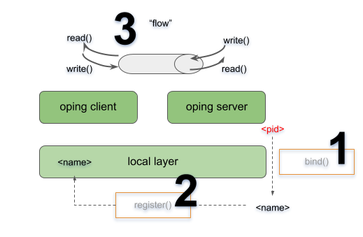 - -We will start the IRMd, create a local IPCP, start a ping server and -connect a client. This will involve **binding (1)** that server to a -name and **registering (2)** that name into the local layer. After that -the client will be able to **allocate a flow (3)** to that name for -which the server will respond. - -We recommend to open 3 terminal windows for this tutorial. In the first -window, start the IRMd (as a superuser) in stdout mode. The output shows -the process id (pid) of the IRMd, which will be different on your -machine. - -``` -$ sudo irmd --stdout -==02301== irmd(II): Ouroboros IPC Resource Manager daemon started\... -``` - -The type of IPCP we will create is a "local" IPCP. The local IPCP is a -kind of loopback interface that is native to Ouroboros. It implements -all the functions that the Ouroboros API provides, but only for a local -scope. The IPCP create function will instantiate a new local IPC -process, which in our case has pid 2324. The "ipcp create" command -merely creates the IPCP. At this point it is not a part of a layer. We -will also need to bootstrap this IPCP in a layer, we will name it -"local_layer". As a shortcut, the bootstrap command will -automatically create an IPCP if no IPCP by than name exists, so in this -case, the IPCP create command is optional. In the second terminal, enter -the commands: - -``` -$ irm ipcp create type local name local_ipcp -$ irm ipcp bootstrap type local name local_ipcp layer local_layer -``` - -The IRMd and ipcpd output in the first terminal reads: - -``` -==02301== irmd(II): Created IPCP 2324. -==02324== ipcpd-local(II): Bootstrapped local IPCP with pid 2324. -==02301== irmd(II): Bootstrapped IPCP 2324 in layer local_layer. -``` - -From the third terminal window, let's start our oping application in -server mode ("oping --help" shows oping command line parameters): - -``` -$ oping --listen -Ouroboros ping server started. -``` - -The IRMd will notice that an oping server with pid 10539 has started: - -``` -==02301== irmd(DB): New instance (10539) of oping added. -==02301== irmd(DB): This process accepts flows for: -``` - -The server application is not yet reachable by clients. Next we will -bind the server to a name and register that name in the -"local_layer". The name for the server can be chosen at will, let's -take "oping_server". In the second terminal window, execute: - -``` -$ irm bind proc 2337 name oping_server -$ irm register name oping_server layer local_layer -``` - -The IRMd and IPCPd in terminal one will now acknowledge that the name is -bound and registered: - -``` -==02301== irmd(II): Bound process 2337 to name oping_server. -==02324== ipcpd-local(II): Registered 4721372d. -==02301== irmd(II): Registered oping_server in local_layer as -4721372d. -``` - -Ouroboros registers name not in plaintext but using a (configurable) -hashing algorithm. The default hash is a 256 bit SHA3 hash. The output -in the logs is truncated to the first 4 bytes in a HEX notation. - -Now that we have bound and registered our server, we can connect from -the client. In the second terminal window, start an oping client with -destination oping_server and it will begin pinging: - -``` -$ oping -n oping_server -c 5 -Pinging oping_server with 64 bytes of data: - -64 bytes from oping_server: seq=0 time=0.694 ms -64 bytes from oping_server: seq=1 time=0.364 ms -64 bytes from oping_server: seq=2 time=0.190 ms -64 bytes from oping_server: seq=3 time=0.269 ms -64 bytes from oping_server: seq=4 time=0.351 ms - ---- oping_server ping statistics --- -5 SDUs transmitted, 5 received, 0% packet loss, time: 5001.744 ms -rtt min/avg/max/mdev = 0.190/0.374/0.694/0.192 ms -``` - -The server will acknowledge that it has a new flow connected on flow -descriptor 64, which will time out a few seconds after the oping client -stops sending: - -``` -New flow 64. -Flow 64 timed out. -``` - -The IRMd and IPCP logs provide some additional output detailing the flow -allocation process: - -``` -==02324== ipcpd-local(DB): Allocating flow to 4721372d on fd 64. -==02301== irmd(DB): Flow req arrived from IPCP 2324 for 4721372d. -==02301== irmd(II): Flow request arrived for oping_server. -==02324== ipcpd-local(II): Pending local allocation request on fd 64. -==02301== irmd(II): Flow on port_id 0 allocated. -==02324== ipcpd-local(II): Flow allocation completed, fds (64, 65). -==02301== irmd(II): Flow on port_id 1 allocated. -==02301== irmd(DB): New instance (2337) of oping added. -==02301== irmd(DB): This process accepts flows for: -==02301== irmd(DB): oping_server -``` - -First, the IPCPd shows that it will allocate a flow towards a -destination hash "4721372d" (truncated). The IRMd logs that IPCPd 2324 -(our local IPCPd) requests a flow towards any process that is listening -for "4721372d", and resolves it to "oping_server", as that is a -process that is bound to that name. At this point, the local IPCPd has a -pending flow on the client side. Since this is the first port_id in the -system, it has port_id 0. The server will accept the flow and the other -end of the flow gets port_id 1. The local IPCPd sees that the flow -allocation is completed. Internally it sees the endpoints as flow -descriptors 64 and 65 which map to port_id 0 and port_id 1. The IPCP -cannot directly access port_ids, they are assigned and managed by the -IRMd. After it has accepted the flow, the oping server enters -flow_accept() again. The IRMd notices the instance and reports that it -accepts flows for "oping_server". - -This concludes this first short tutorial. All running processes can be -terminated by issuing a Ctrl-C command in their respective terminals or -you can continue with the next tutorial. diff --git a/content/docs/tutorials/tutorial-2.md b/content/docs/tutorials/tutorial-2.md deleted file mode 100644 index c3925dc..0000000 --- a/content/docs/tutorials/tutorial-2.md +++ /dev/null @@ -1,298 +0,0 @@ ---- -title: "Tutorial 2: Adding a layer" -draft: false ---- - -In this tutorial we will add a __unicast layer__ on top of the local -layer. Make sure you have a [local -layer](/docs/tutorials/tutorial-1/) running. The network will look -like this: - - - -Let's start adding the unicast layer. We will first bootstrap a -unicast IPCP, with name "U1" into the layer "U" (using -default options). In terminal 2, type: - -``` -$ irm ipcp bootstrap type unicast name U1 layer U -``` - -The IRMd and IPCP will report the bootstrap: - -``` -==02301== irmd(II): Created IPCP 4363. -==04363== normal-ipcp(DB): IPCP got address 465922905. -==04363== directory(DB): Bootstrapping directory. -==04363== directory(II): Directory bootstrapped. -==04363== normal-ipcp(DB): Bootstrapped in layer normal_layer. -==02301== irmd(II): Bootstrapped IPCP 4363 in layer normal_layer. -==02301== irmd(DB): New instance (4363) of ipcpd-normal added. -==02301== irmd(DB): This process accepts flows for: -``` - -The new IPCP has pid 4363. It also generated an *address* for itself, -465922905. Then it bootstrapped a directory. The directory will map -registered names to an address or a set of addresses. In the normal DHT -the current default (and only option) for the directory is a Distributed -Hash Table (DHT) based on the Kademlia protocol, similar to the DHT used -in the mainline BitTorrent as specified by the -[BEP5](http://www.bittorrent.org/beps/bep_0005.html). This DHT will use -the hash algorithm specified for the layer (default is 256-bit SHA3) -instead of the SHA1 algorithm used by Kademlia. Just like any -Ouroboros-capable process, the IRMd will notice a new instance of the -normal IPCP. We will now bind this IPCP to some names and register them -in the local_layer: - -``` -$ irm bind ipcp normal_1 name normal_1 -$ irm bind ipcp normal_1 name normal_layer -$ irm register name normal_1 layer local_layer -$ irm register name normal_layer layer local_layer -``` - -The "irm bind ipcp" call is a shorthand for the "irm bind proc" call -that uses the ipcp name instead of the pid for convenience. Note that -we have bound the same process to two different names. This is to -allow enrollment using a layer name (anycast) instead of a specific -ipcp_name. The IRMd and local IPCP should log the following, just as -in tutorial 1: - -``` -==02301== irmd(II): Bound process 4363 to name normal_1. -==02301== irmd(II): Bound process 4363 to name normal_layer. -==02324== ipcpd-local(II): Registered e9504761. -==02301== irmd(II): Registered normal_1 in local_layer as e9504761. -==02324== ipcpd-local(II): Registered f40ee0f0. -==02301== irmd(II): Registered normal_layer in local_layer as -f40ee0f0. -``` - -We will now create a second IPCP and enroll it in the normal_layer. -Like the "irm ipcp bootstrap command", the "irm ipcp enroll" command -will create the IPCP if an IPCP with that name does not yet exist in the -system. An "autobind" option is a shorthand for binding the IPCP to -the IPCP name and the layer name. - -``` -$ irm ipcp enroll name normal_2 layer normal_layer autobind -``` - -The activity is shown by the output of the IRMd and the IPCPs. Let's -break it down. First, the new normal IPCP is created and bound to its -process name: - -``` -==02301== irmd(II): Created IPCP 13569. -==02301== irmd(II): Bound process 13569 to name normal_2. -``` - -Next, that IPCP will *enroll* with an existing member of the layer -"normal_layer". To do that it first allocates a flow over the local -layer: - -``` -==02324== ipcpd-local(DB): Allocating flow to f40ee0f0 on fd 64. -==02301== irmd(DB): Flow req arrived from IPCP 2324 for f40ee0f0. -==02301== irmd(II): Flow request arrived for normal_layer. -==02324== ipcpd-local(II): Pending local allocation request on fd 64. -==02301== irmd(II): Flow on port_id 0 allocated. -==02324== ipcpd-local(II): Flow allocation completed, fds (64, 65). -==02301== irmd(II): Flow on port_id 1 allocated. -``` - -Over this flow, it connects to the enrollment component of the normal_1 -IPCP. It sends some information that it will speak the Ouroboros -Enrollment Protocol (OEP). Then it will receive boot information from -normal_1 (the configuration of the layer that was provided when we -bootstrapped the normal_1 process), such as the hash it will use for -the directory. It signals normal_1 that it got the information so that -normal_1 knows this was successful. It will also get an address. After -enrollment is complete, both normal_1 and normal_2 will be ready to -accept incoming flows: - -``` -==13569== connection-manager(DB): Sending cacep info for protocol OEP to -fd 64. -==13569== enrollment(DB): Getting boot information. -==02301== irmd(DB): New instance (4363) of ipcpd-normal added. -==02301== irmd(DB): This process accepts flows for: -==02301== irmd(DB): normal_layer -==02301== irmd(DB): normal_1 -==04363== enrollment(DB): Enrolling a new neighbor. -==04363== enrollment(DB): Sending enrollment info (49 bytes). -==13569== enrollment(DB): Received enrollment info (49 bytes). -==13569== normal-ipcp(DB): IPCP got address 416743497. -==04363== enrollment(DB): Neighbor enrollment successful. -==02301== irmd(DB): New instance (13569) of ipcpd-normal added. -==02301== irmd(DB): This process accepts flows for: -==02301== irmd(DB): normal_2 -``` - -Now that the member is enrolled, normal_1 and normal_2 will deallocate -the flow over which it enrolled and signal the IRMd that the enrollment -was successful: - -``` -==02301== irmd(DB): Partial deallocation of port_id 0 by process -13569. -==02301== irmd(DB): Partial deallocation of port_id 1 by process 4363. -==02301== irmd(II): Completed deallocation of port_id 0 by process -2324. -==02301== irmd(II): Completed deallocation of port_id 1 by process -2324. -==02324== ipcpd-local(II): Flow with fd 64 deallocated. -==02324== ipcpd-local(II): Flow with fd 65 deallocated. -==13569== normal-ipcp(II): Enrolled with normal_layer. -==02301== irmd(II): Enrolled IPCP 13569 in layer normal_layer. -``` - -Now that normal_2 is a full member of the layer, the irm tool will -complete the autobind option and bind normal_2 to the name -"normal_layer" so it can also enroll new members. - -``` -==02301== irmd(II): Bound process 13569 to name normal_layer. -``` - -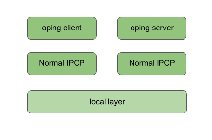 - -At this point, have two enrolled members of the normal_layer. What we -need to do next is connect them. We will need a *management flow*, for -the management network, which is used to distribute point-to-point -information (such as routing information) and a *data transfer flow* -over which the layer will forward traffic coming either from higher -layers or internal components (such as the DHT and flow allocator). They -can be established in any order, but it is recommended to create the -management network first to achieve the minimal setup times for the -network layer: - -``` -$ irm ipcp connect name normal_2 dst normal_1 comp mgmt -$ irm ipcp connect name normal_2 dst normal_1 comp dt -``` - -The IPCP and IRMd log the flow and connection establishment: - -``` -==02301== irmd(DB): Connecting Management to normal_1. -==02324== ipcpd-local(DB): Allocating flow to e9504761 on fd 64. -==02301== irmd(DB): Flow req arrived from IPCP 2324 for e9504761. -==02301== irmd(II): Flow request arrived for normal_1. -==02324== ipcpd-local(II): Pending local allocation request on fd 64. -==02301== irmd(II): Flow on port_id 0 allocated. -==02324== ipcpd-local(II): Flow allocation completed, fds (64, 65). -==02301== irmd(II): Flow on port_id 1 allocated. -==13569== connection-manager(DB): Sending cacep info for protocol LSP to -fd 64. -==04363== link-state-routing(DB): Type mgmt neighbor 416743497 added. -==02301== irmd(DB): New instance (4363) of ipcpd-normal added. -==02301== irmd(DB): This process accepts flows for: -==02301== irmd(DB): normal_layer -==02301== irmd(DB): normal_1 -==13569== link-state-routing(DB): Type mgmt neighbor 465922905 added. -==02301== irmd(II): Established Management connection between IPCP 13569 -and normal_1. -``` - -The IPCPs established a management flow between the link-state routing -components (currently that is the only component that needs a management -flow). The output is similar for the data transfer flow, however, -creating a data transfer flow triggers some additional activity: - -``` -==02301== irmd(DB): Connecting Data Transfer to normal_1. -==02324== ipcpd-local(DB): Allocating flow to e9504761 on fd 66. -==02301== irmd(DB): Flow req arrived from IPCP 2324 for e9504761. -==02301== irmd(II): Flow request arrived for normal_1. -==02324== ipcpd-local(II): Pending local allocation request on fd 66. -==02301== irmd(II): Flow on port_id 2 allocated. -==02324== ipcpd-local(II): Flow allocation completed, fds (66, 67). -==02301== irmd(II): Flow on port_id 3 allocated. -==13569== connection-manager(DB): Sending cacep info for protocol dtp to -fd 65. -==04363== dt(DB): Added fd 65 to SDU scheduler. -==04363== link-state-routing(DB): Type dt neighbor 416743497 added. -==02301== irmd(DB): New instance (4363) of ipcpd-normal added. -==02301== irmd(DB): This process accepts flows for: -==02301== irmd(DB): normal_layer -==02301== irmd(DB): normal_1 -==13569== dt(DB): Added fd 65 to SDU scheduler. -==13569== link-state-routing(DB): Type dt neighbor 465922905 added. -==13569== dt(DB): Could not get nhop for addr 465922905. -==02301== irmd(II): Established Data Transfer connection between IPCP -13569 and normal_1. -==13569== dt(DB): Could not get nhop for addr 465922905. -==13569== dht(DB): Enrollment of DHT completed. -``` - -First, the data transfer flow is added to the SDU scheduler. Next, the -neighbor's address is added to the link-state database and a Link-State -Update message is broadcast over the management network. Finally, if the -DHT is not yet enrolled, it will try to do so when it detects a new data -transfer flow. Since this is the first data transfer flow in the -network, the DHT will try to enroll. It may take some time for the -routing entry to get inserted to the forwarding table, so the DHT -re-tries a couple of times (this is the "could not get nhop" message -in the debug log). - -Our oping server is not registered yet in the normal layer. Let's -register it in the normal layer as well, and connect the client: - -``` -$ irm r n oping_server layer normal_layer -$ oping -n oping_server -c 5 -``` - -The IRMd and IPCP will log: - -``` -==02301== irmd(II): Registered oping_server in normal_layer as -465bac77. -==02301== irmd(II): Registered oping_server in normal_layer as -465bac77. -==02324== ipcpd-local(DB): Allocating flow to 4721372d on fd 68. -==02301== irmd(DB): Flow req arrived from IPCP 2324 for 4721372d. -==02301== irmd(II): Flow request arrived for oping_server. -==02324== ipcpd-local(II): Pending local allocation request on fd 68. -==02301== irmd(II): Flow on port_id 4 allocated. -==02324== ipcpd-local(II): Flow allocation completed, fds (68, 69). -==02301== irmd(II): Flow on port_id 5 allocated. -==02301== irmd(DB): New instance (2337) of oping added. -==02301== irmd(DB): This process accepts flows for: -==02301== irmd(DB): oping_server -==02301== irmd(DB): Partial deallocation of port_id 4 by process 749. -==02301== irmd(II): Completed deallocation of port_id 4 by process -2324. -==02324== ipcpd-local(II): Flow with fd 68 deallocated. -==02301== irmd(DB): Dead process removed: 749. -==02301== irmd(DB): Partial deallocation of port_id 5 by process 2337. -==02301== irmd(II): Completed deallocation of port_id 5 by process -2324. -==02324== ipcpd-local(II): Flow with fd 69 deallocated. -``` - -The client connected over the local layer instead of the normal layer. -This is because the IRMd prefers the local layer. If we unregister the -name from the local layer, the client will connect over the normal -layer: - -``` -$ irm unregister name oping_server layer local_layer -$ oping -n oping_server -c 5 -``` - -As shown by the logs (the normal IPCP doesn't log the flow allocation): - -``` -==02301== irmd(DB): Flow req arrived from IPCP 13569 for 465bac77. -==02301== irmd(II): Flow request arrived for oping_server. -==02301== irmd(II): Flow on port_id 5 allocated. -==02301== irmd(II): Flow on port_id 4 allocated. -==02301== irmd(DB): New instance (2337) of oping added. -==02301== irmd(DB): This process accepts flows for: -==02301== irmd(DB): oping_server -``` - -This concludes tutorial 2. You can shut down everything or continue with -tutorial 3. diff --git a/content/docs/tutorials/tutorial-3.md b/content/docs/tutorials/tutorial-3.md deleted file mode 100644 index 2dd0645..0000000 --- a/content/docs/tutorials/tutorial-3.md +++ /dev/null @@ -1,210 +0,0 @@ ---- -title: "Tutorial 3: IPCP statistics" -draft: false ---- - -For this tutorial, you should have a local layer, a normal layer and a -ping server registered in the normal layer. You will need to have the -FUSE libraries installed and Ouroboros compiled with FUSE support. We -will show you how to get some statistics from the network layer which is -exported by the IPCPs at /tmp/ouroboros (this mountpoint can be set at -compile time): - -``` -$ tree /tmp/ouroboros -/tmp/ouroboros/ -|-- ipcpd-normal.13569 -| |-- dt -| | |-- 0 -| | |-- 1 -| | `-- 65 -| `-- lsdb -| |-- 416743497.465922905 -| |-- 465922905.416743497 -| |-- dt.465922905 -| `-- mgmt.465922905 -`-- ipcpd-normal.4363 - |-- dt - | |-- 0 - | |-- 1 - | `-- 65 - `-- lsdb - |-- 416743497.465922905 - |-- 465922905.416743497 - |-- dt.416743497 - `-- mgmt.416743497 - -6 directories, 14 files -``` - -There are two filesystems, one for each normal IPCP. Currently, it shows -information for two components: data transfer and the link-state -database. The data transfer component lists flows on known flow -descriptors. The flow allocator component will usually be on fd 0 and -the directory (DHT). There is a single (N-1) data transfer flow on fd 65 -that the IPCPs can use to send data (these fd's will usually not be the -same). The routing component sees that data transfer flow as two -unidirectional links. It has a management flow and data transfer flow to -its neighbor. Let's have a look at the data transfer flow in the -network: - -``` -$ cat /tmp/ouroboros/ipcpd-normal.13569/dt/65 -Flow established at: 2018-03-07 18:47:43 -Endpoint address: 465922905 -Queued packets (rx): 0 -Queued packets (tx): 0 - -Qos cube 0: - sent (packets): 4 - sent (bytes): 268 - rcvd (packets): 3 - rcvd (bytes): 298 - local sent (packets): 4 - local sent (bytes): 268 - local rcvd (packets): 3 - local rcvd (bytes): 298 - dropped ttl (packets): 0 - dropped ttl (bytes): 0 - failed writes (packets): 0 - failed writes (bytes): 0 - failed nhop (packets): 0 - failed nhop (bytes): 0 - -<no traffic on other qos cubes> -``` - -The above output shows the statistics for the data transfer component of -the IPCP that enrolled into the layer. It shows the time the flow was -established, the endpoint address and the number of packets that are in -the incoming and outgoing queues. Then it lists packet statistics per -QoS cube. It sent 4 packets, and received 3 packets. All the packets -came from local sources (internal components of the IPCP) and were -delivered to local destinations. Let's have a look where they went. - -``` -$ cat /tmp/ouroboros/ipcpd-normal.13569/dt/1 -Flow established at: 2018-03-07 18:47:43 -Endpoint address: flow-allocator -Queued packets (rx): 0 -Queued packets (tx): 0 - -<no packets on this flow> -``` - -There is no traffic on fd 0, which is the flow allocator component. This -will only be used when higher layer applications will use this normal -layer. Let's have a look at fd 1. - -``` -$ cat /tmp/ouroboros/ipcpd-normal.13569/dt/1 -Flow established at: 2018-03-07 18:47:43 -Endpoint address: dht -Queued packets (rx): 0 -Queued packets (tx): 0 - -Qos cube 0: - sent (packets): 3 - sent (bytes): 298 - rcvd (packets): 0 - rcvd (bytes): 0 - local sent (packets): 0 - local sent (bytes): 0 - local rcvd (packets): 6 - local rcvd (bytes): 312 - dropped ttl (packets): 0 - dropped ttl (bytes): 0 - failed writes (packets): 0 - failed writes (bytes): 0 - failed nhop (packets): 2 - failed nhop (bytes): 44 - -<no traffic on other qos cubes> -``` - -The traffic for the directory (DHT) is on fd1. Take note that this is -from the perspective of the data transfer component. The data transfer -component sent 3 packets to the DHT, these are the 3 packets it received -from the data transfer flow. The data transfer component received 6 -packets from the DHT. It only sent 4 on fd 65. 2 packets failed because -of nhop. This is because the forwarding table was being updated from the -routing table. Let's send some traffic to the oping server. - -``` -$ oping -n oping_server -i 0 -Pinging oping_server with 64 bytes of data: - -64 bytes from oping_server: seq=0 time=0.547 ms -... -64 bytes from oping_server: seq=999 time=0.184 ms - ---- oping_server ping statistics --- -1000 SDUs transmitted, 1000 received, 0% packet loss, time: 106.538 ms -rtt min/avg/max/mdev = 0.151/0.299/2.269/0.230 ms -``` - -This sent 1000 packets to the server. Let's have a look at the flow -allocator: - -``` -$ cat /tmp/ouroboros/ipcpd-normal.13569/dt/0 -Flow established at: 2018-03-07 18:47:43 -Endpoint address: flow-allocator -Queued packets (rx): 0 -Queued packets (tx): 0 - -Qos cube 0: - sent (packets): 1 - sent (bytes): 59 - rcvd (packets): 0 - rcvd (bytes): 0 - local sent (packets): 0 - local sent (bytes): 0 - local rcvd (packets): 1 - local rcvd (bytes): 51 - dropped ttl (packets): 0 - dropped ttl (bytes): 0 - failed writes (packets): 0 - failed writes (bytes): 0 - failed nhop (packets): 0 - failed nhop (bytes): 0 - -<no traffic on other qos cubes> -``` - -The flow allocator has sent and received a message: a request and a -response for the flow allocation between the oping client and server. -The data transfer flow will also have additional traffic: - -``` -$ cat /tmp/ouroboros/ipcpd-normal.13569/dt/65 -Flow established at: 2018-03-07 18:47:43 -Endpoint address: 465922905 -Queued packets (rx): 0 -Queued packets (tx): 0 - -Qos cube 0: - sent (packets): 1013 - sent (bytes): 85171 - rcvd (packets): 1014 - rcvd (bytes): 85373 - local sent (packets): 13 - local sent (bytes): 1171 - local rcvd (packets): 14 - local rcvd (bytes): 1373 - dropped ttl (packets): 0 - dropped ttl (bytes): 0 - failed writes (packets): 0 - failed writes (bytes): 0 - failed nhop (packets): 0 - failed nhop (bytes): 0 -``` - -This shows the traffic from the oping application. The additional -traffic (the oping sent 1000, the flow allocator 1 and the DHT -previously sent 3) is additional DHT traffic (the DHT periodically -updates). Also note that the traffic reported on the link includes the -FRCT and data transfer headers which in the default configuration is 20 -bytes per packet. - -This concludes tutorial 3. diff --git a/content/docs/tutorials/tutorial-4.md b/content/docs/tutorials/tutorial-4.md deleted file mode 100644 index fd7db3a..0000000 --- a/content/docs/tutorials/tutorial-4.md +++ /dev/null @@ -1,123 +0,0 @@ ---- -title: "Tutorial 4: Connecting two machines over Ethernet" -draft: false ---- - -In this tutorial we will connect two machines over an Ethernet network -using the eth-llc or eth-dix IPCPs. The eth-llc use of the IEEE 802.2 -Link Layer Control (LLC) service type 1 frame header. The eth-dix IPCP -uses DIX (DEC, Intel, Xerox) Ethernet, also known as Ethernet II. Both -provide a connectionless packet service with unacknowledged delivery. - -Make sure that you have an Ouroboros IRM daemon running on both -machines: - -``` -$ sudo irmd --stdout -``` - -The eth-llc and eth-dix IPCPs attach to an ethernet interface, which is -specified by its device name. The device name can be found in a number -of ways, we'll use the "ip" command here: - -``` -$ ip a -1: lo: <LOOPBACK,UP,LOWER_UP> mtu 65536 qdisc noqueue state UNKNOWN -group default qlen 1 -link/loopback 00:00:00:00:00:00 brd 00:00:00:00:00:00 -... -2: ens3: <BROADCAST,MULTICAST,UP,LOWER_UP> mtu 1500 qdisc pfifo_fast -state UP group default qlen 1000 -link/ether fa:16:3e:42:00:38 brd ff:ff:ff:ff:ff:ff -... -3: ens6: <BROADCAST,MULTICAST,UP,LOWER_UP> mtu 1500 qdisc pfifo_fast -state UP group default qlen 1000 -link/ether fa:16:3e:00:76:c2 brd ff:ff:ff:ff:ff:ff -... -``` - -The output of this command differs between operating systems and -distributions. The interface we need to use in our setup is "ens3" on -both machines, but for you it may be something like "eth0" or -"enp0s7f1" if you are on a wired LAN, or something like "wlan0" or -"wlp2s0" if you are on a Wi-Fi network. For Wi-Fi networks, we -recommend using the eth-dix. - -Usually the interface you will use is the one that has an IP address for -your LAN set. Note that you do not need to have an IP address for this -tutorial, but do make sure the interface is UP. - -Now that we know the interfaces to connect to the network with, let's -start the eth-llc/eth-dix IPCPs. The eth-llc/eth-dix layers don't have -an enrollment phase, all eth-llc IPCPs that are connected to the same -Ethernet, will be part of the layer. For eth-dix IPCPs the layers can be -separated by ethertype. The eth-llc and eth-dix IPCPs can only be -bootstrapped, so care must be taken by to provide the same hash -algorithm to all eth-llc and eth-dix IPCPs that should be in the same -network. We use the default (256-bit SHA3) for the hash and 0xa000 for -the Ethertype for the DIX IPCP. For our setup, it's the exact same -command on both machines. You will likely need to set a different -interface name on each machine. The irm tool allows abbreviated commands -(it is modelled after the "ip" command), which we show here (both -commands do the same): - -``` -node0: $ irm ipcp bootstrap type eth-llc name llc layer eth dev ens3 -node1: $ irm i b t eth-llc n llc l eth if ens3 -``` - -Both IRM daemons should acknowledge the creation of the IPCP: - -``` -==26504== irmd(II): Ouroboros IPC Resource Manager daemon started... -==26504== irmd(II): Created IPCP 27317. -==27317== ipcpd/eth-llc(II): Using raw socket device. -==27317== ipcpd/eth-llc(DB): Bootstrapped IPCP over Ethernet with LLC -with pid 27317. -==26504== irmd(II): Bootstrapped IPCP 27317 in layer eth. -``` - -If it failed, you may have mistyped the interface name, or your system -may not have a valid raw packet API. We are using GNU/Linux machines, so -the IPCP announces that it is using a [raw -socket](http://man7.org/linux/man-pages/man2/socket.2.html) device. On -OS X, the default is a [Berkeley Packet Filter -(BPF)](http://www.manpages.info/macosx/bpf.4.html) device, and on -FreeBSD, the default is a -[netmap](http://info.iet.unipi.it/~luigi/netmap/) device. See the -[compilation options](/compopt) for more information on choosing the -raw packet API. - -The Ethernet layer is ready to use. We will now create a normal layer -on top of it, just like we did over the local layer in the second -tutorial. We are showing some different ways of entering these -commands on the two machines: - -``` -node0: -$ irm ipcp bootstrap type normal name normal_0 layer normal_layer -$ irm bind ipcp normal_0 name normal_0 -$ irm b i normal_0 n normal_layer -$ irm register name normal_layer layer eth -$ irm r n normal_0 l eth -node1: -$ irm ipcp enroll name normal_1 layer normal_layer autobind -$ irm r n normal_layer l eth -$ irm r n normal_1 l eth -``` - -The IPCPs should acknowledge the enrollment in their logs: - -``` -node0: -==27452== enrollment(DB): Enrolling a new neighbor. -==27452== enrollment(DB): Sending enrollment info (47 bytes). -==27452== enrollment(DB): Neighbor enrollment successful. -node1: -==27720== enrollment(DB): Getting boot information. -==27720== enrollment(DB): Received enrollment info (47 bytes). -``` - -You can now continue to set up a management flow and data transfer -flow for the normal layer, like in tutorial 2. This concludes the -fourth tutorial. diff --git a/content/docs/what.md b/content/docs/what.md deleted file mode 100644 index b30b17c..0000000 --- a/content/docs/what.md +++ /dev/null @@ -1,152 +0,0 @@ ---- -title: "What is a recursive network?" -author: "Dimitri Staessens" -description: "what" -date: 2019-07-06 -#type: page -draft: false ---- - -# The current networking paradigm - -<center> {{<figure -class="w-80" -src="/images/aschenbrenner.png">}} -</center> - -Every computer science class that deals with networks explains the -[7-layer OSI model](https://www.bmc.com/blogs/osi-model-7-layers/). -Open Systems Interconnect (OSI) defines 7 layers, each providing an -abstraction for a certain *function* that a network application may -need. - -From top to bottom, the layers provide (roughly) the following -functions: - -The __application layer__ implements the details of the application -protocol (such as HTTP), which specifies the operations and data that -the application understands (requesting a web page). - -The __presentation layer__ provides independence of data representation, -and may also perform encryption. - -The __session layer__ sets up and manages sessions (think of a session -as a conversation or dialogue) between the applications. - -The __transport layer__ handles individual chunks of data (think of them -as words in the conversation), and can ensure that there is end-to-end -reliability (no words or phrases get lost). - -The __network layer__ forwards the packets across the network, it -provides such things as addressing and congestion control. - -The __datalink layer__ encodes data into bits and moves them between -hosts. It handles errors in the physical layer. It has two sub-layers: -Media access control layer (MAC), which says when hosts can transmit -on the medium, and logical link control (LLC) that deals with error -handling and control of transmission rates. - -Finally, the __physical layer__ is responsible for translating the -bits into a signal (e.g. laser pulses in a fibre) that is carried -between endpoints. - -This functional layering provides a logical order for the steps that -data passes through between applications. Indeed, every existing -(packet) network goes through these steps in roughly this order -(however, some may be skipped). There can be some small variations on -where the functions are implemented. For instance, TCP does congestion -control, but is a Layer 4 protocol. - -However, when looking at current networking solutions, things are not -as simple as these 7 layers seem to indicate. Just consider this -realistic scenario for a software developer working remotely. Usually -it goes something like this: You connect to the company __Virtual -Private Network__ (VPN), setup an SSH __tunnel__ over the development -server to your virtual machine and then SSH into that virtual machine. - -The use of VPNs and various tunneling technologies draw a picture -where the __functions__ of Layers 2, 3, and 4, and often layers 5 and -6 (encryption) are __repeated__ a number of times in the actual -functional path that data follows through the network stack. - -Enter __*recursive networks*__. - -# The recursive network paradigm - -The functional repetition in the network stack is discussed in -detail in the book __*"Patterns in Network Architecture: A Return to -Fundamentals"*__. From the observations in the book, a new architecture -was proposed, called the "__R__ecursive __I__nter__N__etwork -__A__rchitecture", or [__RINA__](http://www.pouzinsociety.org). - -__Ouroboros__ follows the recursive principles of RINA, but deviates -quit a bit from its internal design. There are resources on the -Internet explaining RINA, but here we will focus -on its high level design and what is relevant for Ouroboros. - -Let's look at a simple scenario of an employee contacting an internet -corporate server over a Layer 3 VPN from home. Let's assume for -simplicity that the corporate LAN is not behind a NAT firewall. All -three networks perform (among some other things): - -__Addressing__: The VPN hosts receive an IP address in the VPN, let's -say some 10.11.12.0/24 address. The host will also have a public IP -address, for instance in the 20.128.0.0/16 range . Finally that host -will have an Ethernet MAC address. Now the addresses __differ in -syntax and semantics__, but for the purpose of moving data packets, -they have the same function: __identifying a node in a network__. - -__Forwarding__: Forwarding is the process of moving packets to a -destination __with intent__: each forwarding action moves the data -packet __closer__ to its destination node with respect to some -__metric__ (distance function). - -__Network discovery__: Ethernet switches learn where the endpoints are -through MAC learning, remembering the incoming interface when it sees -a new SRC address; IP routers learn the network by exchanging -informational packets about adjacency in a process called *routing*; -and a VPN proxy server relays packets as the central hub of a network -connected as a star between the VPN clients and the local area -network (LAN) that is provides access to. - -__Congestion management__: When there is a prolonged period where a -node receives more traffic than can forward forward, for instance -because there are incoming links with higher speeds than some outgoing -link, or there is a lot of traffic between different endpoints towards -the same destination, the endpoints experience congestion. Each -network could handle this situation (but not all do: TCP does -congestion control for IP networks, but Ethernet just drops traffic -and lets the IP network deal with it. Congestion management for -Ethernet never really took off). - -__Name resolution__: In order not having to remember addresses of the -hosts (which are in a format that make it easier for a machine to deal -with), each network keeps a mapping of a name to an address. For IP -networks (which includes the VPN in our example), this is done by the -Domain Name System (DNS) service (or, alternatively, other services -such as *open root* or *namecoin*). For Ethernet, the Address -Resolution Protocol maps a higher layer name to a MAC (hardware) -address. - -<center> -{{<figure class="fl w-90" - src="/images/layers.jpg">}} -</center> - -Recursive networks take all these functions to be part of a network -layer, and layers are mostly defined by their __scope__. The lowest -layers span a link or the reach of some wireless technology. Higher -layers span a LAN or the network of a corporation e.g. a subnetwork or -an Autonomous System (AS). An even higher layer would be a global -network, followed by a Virtual Private Network and on top a tunnel -that supports the application. Each layer being the same in terms of -functionality, but different in its choice of algorithm or -implementation. Sometimes the function is just not implemented -(there's no need for routing in a tunnel!), but logically it could be -there. - - ---- -Changelog: - -2019 07 09: Initial version.
\ No newline at end of file |