DOCUMENTATION
Elements of a recursive network
This section describes the high-level concepts and building blocks are used to construct a decentralized recursive network: layers and flows. (Ouroboros has two different kinds of layers, but we will dig into all the fine details in later posts).
A layer in a recursive network embodies all of the functionalities that are currently in layers 3 and 4 of the OSI model (along with some other functions). The difference is subtle and takes a while to get used to (not unlike the differences in the term variable in imperative versus functional programming languages). A recursive network layer handles requests for communication to some remote process and, as a result, it either provides a handle to a communication channel – a flow endpoint –, or it raises some error that no such flow could be provided.
A layer in Ouroboros is built up from a bunch of (identical) programs that work together, called Inter-Process Communication (IPC) Processes (IPCPs). The name “IPCP” was first coined for a component of the LINCS hierarchical network architecture built at Lawrence Livermore National Laboratories and was taken over in the RINA architecture. These IPCPs implement the core functionalities (such as routing, a dictionary) and can be seen as small virtual routers for the recursive network.

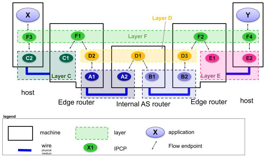
In the illustration, a small 5-node recursive network is shown. It consists of two hosts that connect via edge routers to a small core. There are 6 layers in this network, labelled A to F.
On the right-hand end-host, a server program Y is running (think a mail server program), and the (mail) client X establishes a flow to Y over layer F (only the endpoints are drawn to avoid cluttering the image).
Now, how does the layer F get the messages from X to Y? There are 4 IPCPs (F1 to F4) in layer F, that work together to provide the flow between the applications X and Y. And how does F3 get the info to F4? That is where the recursion comes in. A layer at some level (its rank), will use flows from another layer at a lower level. The rank of a layer is a local value. In the hosts, layer F is at rank 1, just above layer C or layer _E. In the edge router, layer F is at rank 2, because there is also layer D in that router. So the flow between X and Y is supported by flows in layer C, D and E, and the flows in layer D are supported by flows in layers A and B.
Of course these dependencies can’t go on forever. At the lowest level, layers A, B, C and E don’t depend on a lower layer anymore, and are sometimes called 0-layers. They only implement the functions to provide flows, but internally, they are specifically tailored to a transmission technology or a legacy network technology. Ouroboros supports such layers over (local) shared memory, over the User Datagram Protocol, over Ethernet and a prototype that supports flows over an Ethernet FPGA device. This allows Ouroboros to integrate with existing networks at OSI layers 4, 2 and 1.
If we then complete the picture above, when X sends a packet to Y, it passes it to F3, which uses a flow to F1 that is implemented as a direct flow between C2 and C1. F1 then forwards the packet to F2 over a flow that is supported by layer D. This flow is implemented by two flows, one from D2 to D1, which is supported by layer A, and one from D1 to D3, which is supported by layer B. F2 will forward the packet to F4, using a flow provided by layer E, and F4 then delivers the packet to Y. So the packet moves along the following chain of IPCPs: F3 –> C2 –> C1 –> F1 –> D2 –> A1 –> A2 –> D1 –> B1 –> B2 –> D3 –> F2 –> E1 –> E2 –> F4.

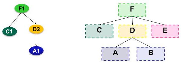
A recursive network has dependencies between layers in the network, and between IPCPs in a system. These dependencies can be represented as a directed acyclic graph (DAG). To avoid problems, these dependencies should never contain cycles (so a layer I should not directly or indirectly depend on itself). The rank of a layer is defined (either locally or globally) as the maximum depth of this layer in the DAG.
Changelog:
2019 07 11: Initial version.
2019 07 23: Added dependency graph figure